

Method for producing a toner, and toner
- Summary
- Abstract
- Description
- Claims
- Application Information
AI Technical Summary
Benefits of technology
Problems solved by technology
Method used
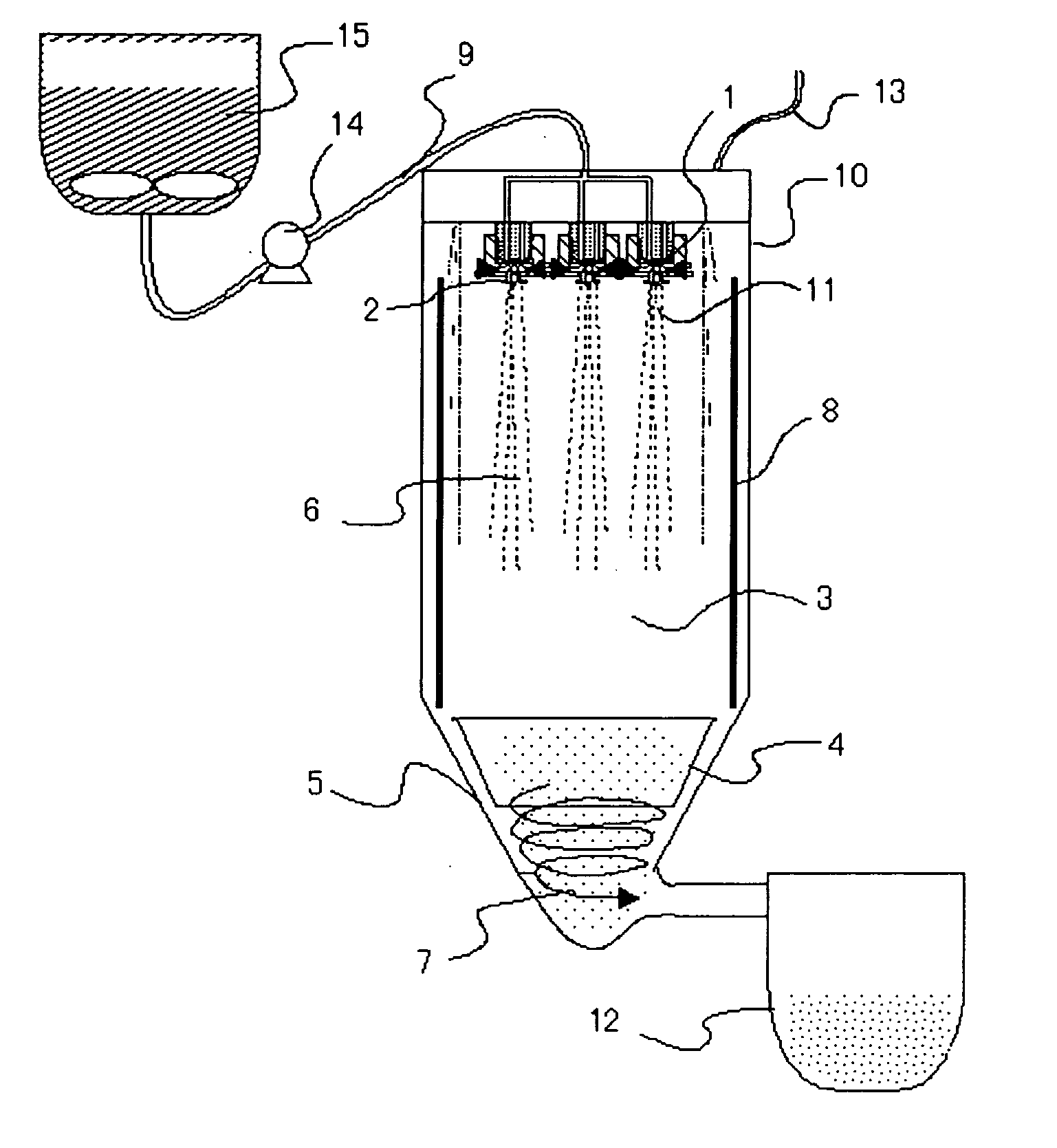
Image

Examples
example 1
-Preparation of Colorant Dispersion-
[0210] First, a dispersion of carbon black was prepared as a colorant dispersion.
[0211] To 82 parts by mass of ethyl acetate, 15 parts by mass of carbon black (Regal 400, manufactured by CABOT Corp.), 3 parts by mass of a pigment dispersing agent was added and primarily dispersed using a mixer having a stirring blade. For the pigment dispersing agent, AJISPER PB821 (manufactured by Ajinomoto Fine-Techno Co., Inc.) was used. The obtained primary dispersion was subjected to a strong shearing force using DYNO MILL to finely disperse the dispersion to thereby prepare a secondary dispersion that the aggregate had been completed removed. Further, the secondary dispersion was passed through a filter having fine pores of 045 μm (manufactured by PTFE) to prepare a dispersion dispersed to submicrons.
-Preparation of Resin and Wax-Added Dispersion-
[0212] Next, a dispersion containing the following composition and to which a resin as a binder resin, and ...
example 2
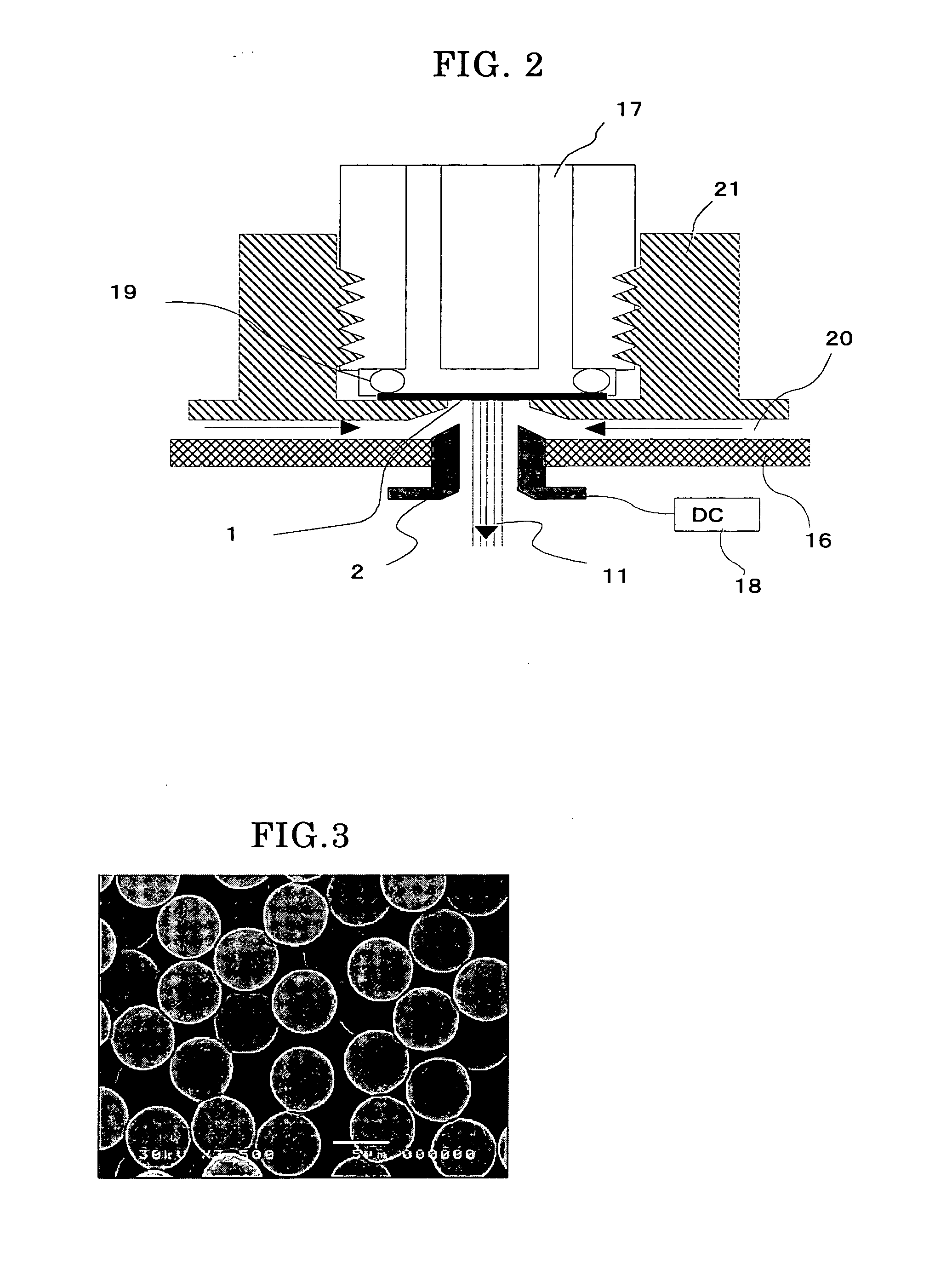
[0236] An intended toner was obtained in the same manner as in Example 1 except that the diameter of the ejection hole was changed to 5 μm, and the concentration of solid parts of the toner was increased to 8 times the concentration of solid parts in Example 1. Consequently, the toner had a weight average particle diameter of 6.0 μm and a number average particle diameter of 6.0 μm, and it was also possible to obtain completely monodisperse toner base particles.
[0237] The obtained toner was evaluated with respect to the properties. Table 1 shows the evaluation results.
example 3
[0238] An intended toner was obtained in the same manner as in Example 1 except that the diameter of the ejection hole was changed to 20 μm, and the concentration of solid parts of the toner was reduced to 0.125 times the concentration of solid parts in Example 1. Consequently, the toner had a weight average particle diameter of 6.0 μm and a number average particle diameter of 6.0 μm, and it was also possible to obtain completely monodisperse toner base particles.
[0239] The obtained toner was evaluated with respect to the properties. Table 1 shows the evaluation results.
PUM
 Abstract
Description
Claims
Application Information