Spread-style coupler

a spread-style, coupler technology, applied in the field of couplers, can solve the problems of deficiency of known spread-style couplers, excessive pivot points, and both hooks pivoting relative to the coupler body

Inactive Publication Date: 2005-04-19
PALADIN BRANDS GROUP
View PDF10 Cites 31 Cited by
  • Summary
  • Abstract
  • Description
  • Claims
  • Application Information

AI Technical Summary

Benefits of technology

[0007]In accordance with another aspect of the present invention, a method of operatively connecting an attachment to a coupler comprises inserting a first attachment pin into a first hook of the coupler and pivoting the coupler about the first attachment pin until a second attachment pin is aligned with a second hook of the co

Problems solved by technology

Known spread-style couplers are deficient for many reasons.
One notable disadvantage of known spread-style couplers is that both hooks pivot relative to the coupler body.
This results in an excessive amount of pivot points and reduces the strength of the coupler.
Similarly, during digging and other operations, large loads are exerted upon the rear

Method used


Image

  • Spread-style coupler
  • Spread-style coupler
  • Spread-style coupler

Examples


Embodiment Construction

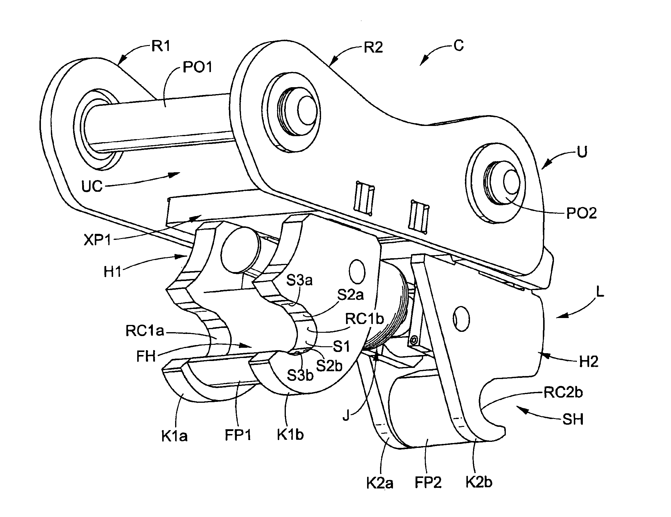
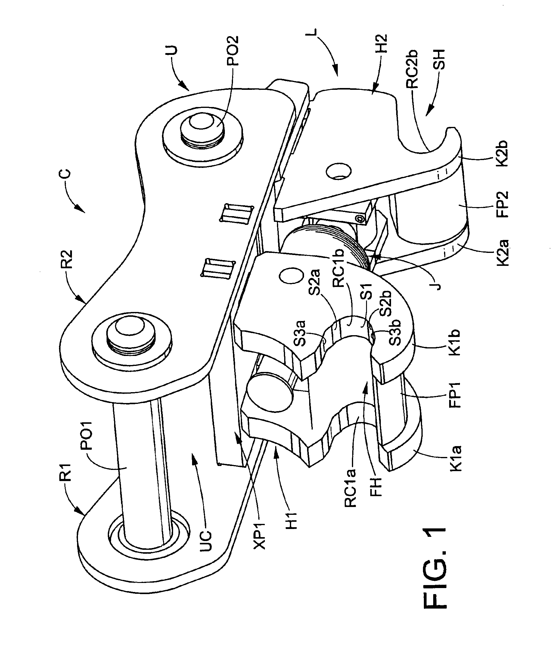
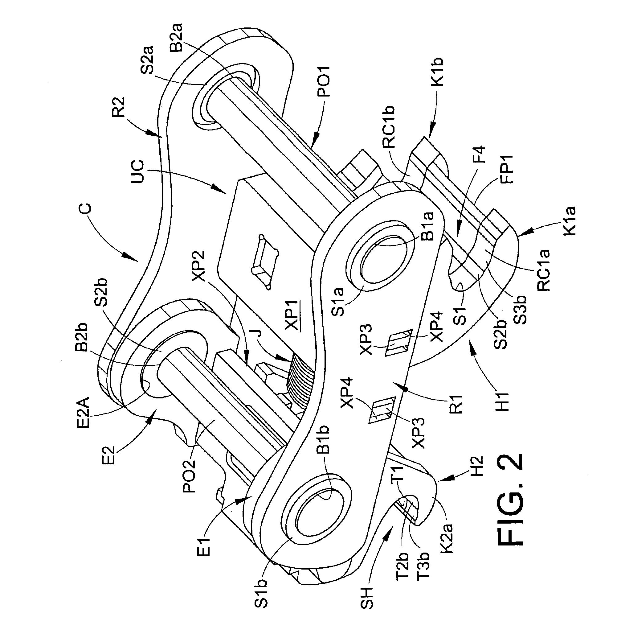
[0025]Referring initially to FIGS. 1-3, a coupler C formed in accordance with the present invention comprises two main sections: (i) an upper section U configured or adapted for pivotable pin-on connection to an arm and control link of an associated excavator, wheel-loader backhoe or any other associated machine having an arm and control link to which the coupler C is operatively connected; and, (ii) a lower section L configured or adapted for releasable operative connection to first and second spaced-apart, parallel pins (see pins P1,P2 in FIGS. 12A-12C) that are connected to an associated bucket, shear, grapple, blade or any other associated attachment. The term “parallel” as used herein is intended to mean exactly parallel and slight variations therefrom as caused by tolerances, minor deformation during welding or use, etc.

[0026]The upper section U comprises first and second parallel spaced-apart ribs R1,R2 that define an open channel UC therebetween. The first rib R1 comprises f...


PUM


Abstract

A coupler includes first and second spaced-apart ribs each defining first and second bores. The first bore of the first rib is aligned with the first bore of the second rib on a first pin-on axis, and the second bore of the first rib aligned with the second bore of the second rib on a second pin-on axis. A first hook assembly includes a first hook adapted to receive a first associated attachment pin. The first hook assembly is fixed relative to the first and second ribs. A second hook assembly includes a second hook adapted to receive a second associated attachment pin. The second hook assembly is selectively pivotable relative to the first and second ribs toward and away from the first hook assembly. An actuator is operatively connected to the second hook assembly to pivot the second hook assembly selectively relative to the first and second ribs.

Description

CROSS-REFERENCE TO RELATED APPLICATION[0001]This application claims priority from and benefit of the filing date of both U.S. provisional application No. 60 / 333,989 filed Nov. 29, 2001 and U.S. provisional application No. 60 / 405,398 filed Aug. 23, 2002.BACKGROUND OF THE INVENTION[0002]The present invention relates to couplers used to secure attachments such as buckets, air-operated hammers, shears, etc. fixedly and operatively to the distal end of a arm of a tractor, backhoe, excavator or other type of arm-equipped construction / agricultural equipment. As is generally well known, couplers are used as an alternative to a pin-on connection for fixedly and operatively securing an implement to the distal end of an arm which is, in turn, secured to a boom of a construction / agricultural machine such as a backhoe or excavator.[0003]Spread-style couplers are generally known. These couplers are connected to an arm by a pin-on connection at a first pivot point and are connected to a control li...

Claims


Application Information

Patent Timeline
IPC IPC(8): E02F3/36
CPCE02F3/3618E02F3/3663E02F3/3622Y10T403/593
Inventor FATEMI, RAY S.
Owner PALADIN BRANDS GROUP
Why Eureka
Try Eureka