Microelectromechanical high pressure gas microvalve

a gas micro-valve, micro-electromechanical technology, applied in the direction of diaphragm valves, engine diaphragms, operating means/release devices of valves, etc., can solve the problems of valves subjected to harsh environments, valves subjected to high temperatures and pressures,

Inactive Publication Date: 2005-04-26
LOCKHEED MARTIN CORP
View PDF6 Cites 35 Cited by
  • Summary
  • Abstract
  • Description
  • Claims
  • Application Information

AI Technical Summary

Benefits of technology

[0006]An object of the present invention is to provide a microvalve that is very well suited for use in harsh environments.
[0008]A further object of the invention is to provide a control mechanism for a microvalve that will effectively and reliably work in a hash environment to open and close the valve at preset pressure levels.
[0009]Still another object of this invention is to provide a microvalve having a combination of robustness against chemical corrosion, high temperature compatibility and high pressure control that makes the valve very well suited for harsh environments.

Problems solved by technology

There are a number of situations in which valves are subjected to harsh environments.
These valves are subjected to very harsh conditions, and specifically, to very high temperatures and pressures and to highly corrosive gases.
Because of this needed highly precise mechanical machining, the valves are very expensive.

Method used


Image

  • Microelectromechanical high pressure gas microvalve
  • Microelectromechanical high pressure gas microvalve
  • Microelectromechanical high pressure gas microvalve

Examples


Embodiment Construction

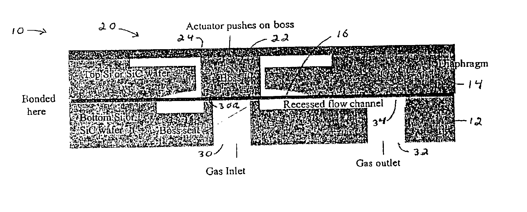
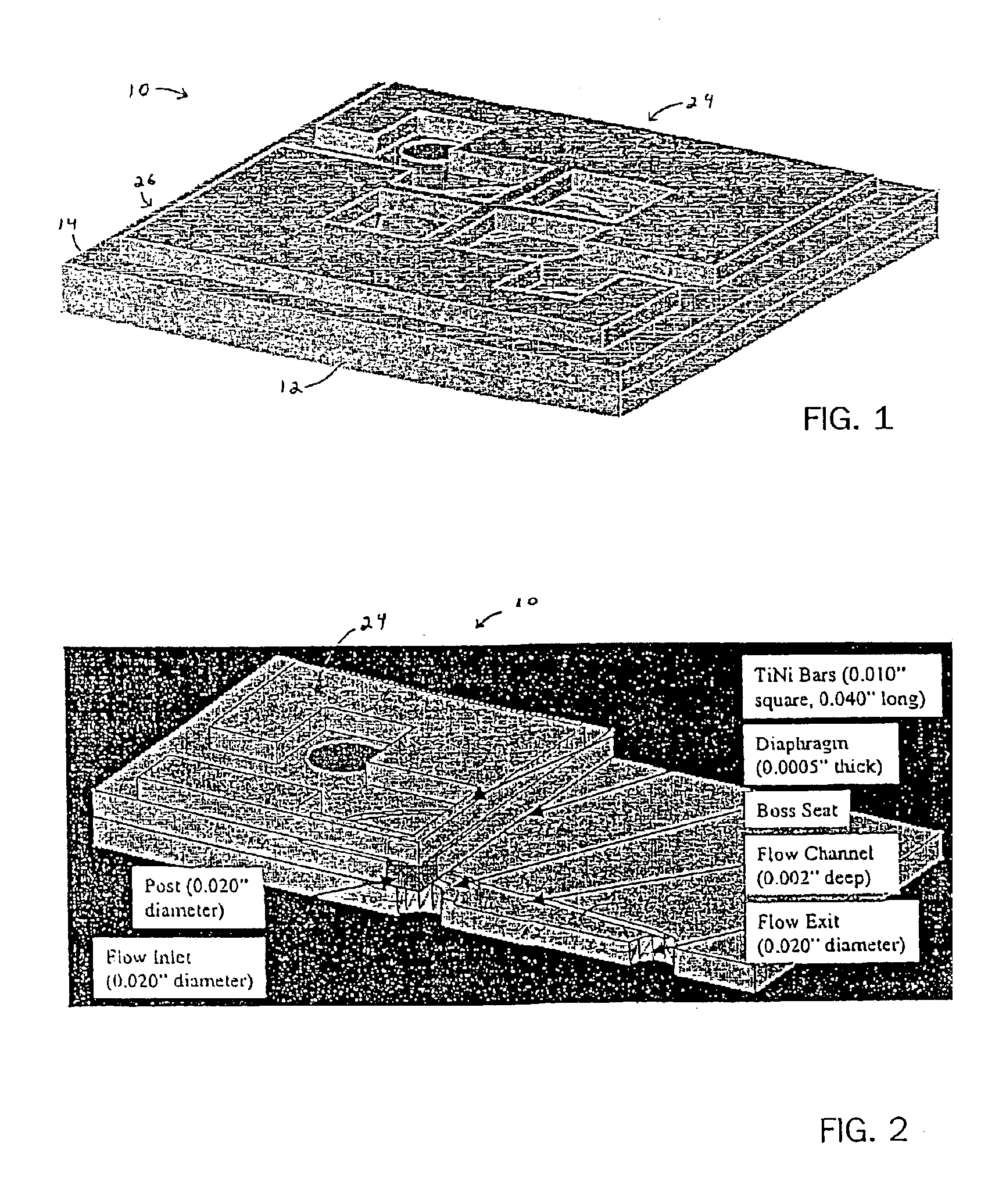
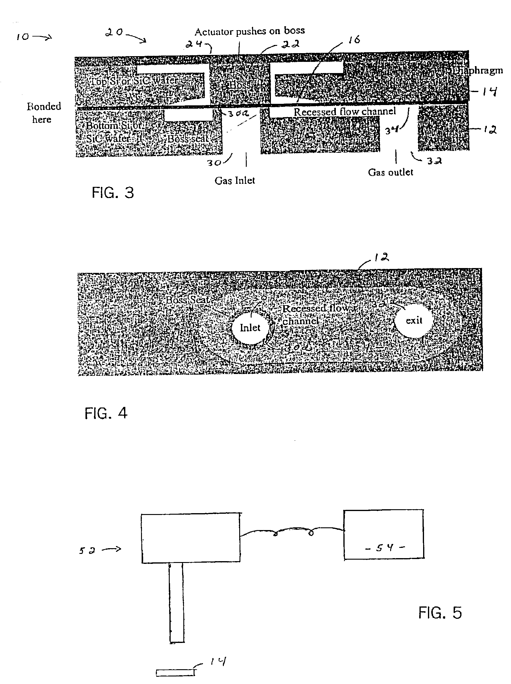
[0022]FIGS. 1-4 show a microvalve 10 generally comprising first and second layers 12 and 14, diaphragm member 16, and switching means 20. Switching means 20, in turn, includes boss 22 and actuation mechanism 24.

[0023]Generally, each of the layers 12 and 14 has a flat thin shape, and the layers are secured together to form a plate or valve body 26. This valve body forms an inlet opening 30 for receiving fluid, an outlet opening 32 for conducting fluid from the valve body, and a flow channel 34 for conducting fluid from the inlet to the outlet. The diaphragm 16 is disposed between the layers 12 and 14, and is moveable between open and closed positions. In the closed position, the diaphragm 16 blocks the flow of fluid from the inlet 30 to the flow channel 34; and in the open position, the diaphragm allows fluid flow from the inlet into that flow channel, allowing fluid flow from the inlet to the outlet 32 of the microvalve. The diaphragm 16 is biased to the closed position, and moves f...


PUM


Abstract

A microvalve and a method of forming a microvalve. The microvalve comprises first and second layers, a diaphragm member and a switching means. The first and second layers are secured together to form a valve body that forms an inlet opening for receiving fluid, an outlet opening for conducting fluid from the valve body, and a flow channel for conducting fluid from the inlet to the outlet. The diaphragm is disposed between the layers, and is movable between open and closed positions. In these position, the diaphragm, respectively, allows and blocks the flow of fluid from the inlet to the flow channel. The diaphragm is biased to the closed position, and moves from the closed position to the open position when the pressure of fluid in the inlet reaches a preset value. The switching means is connected to the valve body for moving the diaphragm to the closed position against the pressure of fluid in the inlet. Preferably, the microvalve is constructed out of SiC and stainless steel materials, allowing the microvalve to be used in a harsh environment.

Description

BACKGROUND OF THE INVENTION[0001]1. Field of the Invention[0002]This invention generally relates to microvalves, and more specifically, to microvalves that are well suited for use in harsh environments.[0003]2. Background Art[0004]There are a number of situations in which valves are subjected to harsh environments. One such application is in rocket engines, where valves are used to direct exhaust gases to help steer the rocket. These valves are subjected to very harsh conditions, and specifically, to very high temperatures and pressures and to highly corrosive gases. In addition to being subjected to these extremely difficult conditions, it is critical that the valves operate precisely in order to accurately steer the rocket. In order to achieve the necessary operating precision, these valves are machined very precisely. Because of this needed highly precise mechanical machining, the valves are very expensive.[0005]It would be desirable if these prior art mechanically machined valve...

Claims


Application Information

Patent Timeline
Patent Type & Authority Patents(United States)
IPC IPC(8): F15C5/00F16K99/00
CPCF15C5/00F16K99/0001F16K99/0007F16K99/0048F16K99/0057F16K99/0015F16K2099/0074
Inventor NIELSEN, MATTHEW C.MEYER, LAURA J.WETZEL, TODD G.WEAVER, STANTON E.FORTIN, JEFFREY B.GUIDA, RENATO
Owner LOCKHEED MARTIN CORP
Why Eureka
Try Eureka