
Wireless network lamp

a technology of wireless network and wires, applied in the field of lamps, can solve the problems of low operation quality of wireless network, too short aerial length, hot issue of wireless network, etc., and achieve the effect of improving signal reception position and expanding the reception area

Inactive Publication Date: 2005-05-03
HSIAO PO SEN
View PDF5 Cites 23 Cited by
  • Summary
  • Abstract
  • Description
  • Claims
  • Application Information

AI Technical Summary

Benefits of technology

[0007]A lamp, comprising a base of the lamp configured with a wireless transmission component. The wireless transmission component having an electric circuit enabled to implement wireless signal reception\transmission. A power cord is connected to a power supply circuit of the electric circuit. An aerial circuit of the electric circuit is connected to a metal stand of the lamp or to a metal frame of a lampshade. A base platform is configured with functionality for transmitting a wireless signal, enabling the lamp to implement wireless signal transmission to equipment having a wireless network card by means of the lamp and wired network equipment. Furthermore, a metal stand of the lamp or a metal frame of a lampshade can extend extent of reception area of an aerial circuit to a better signal reception position.

Problems solved by technology

In recent years wireless networks have become a topic of hot issue.
However, obstruction of peripheral equipment results when an aerial extension protruding from the mini base platform is too long, and too short an aerial length is incapable of normal signal transmission\reception.
Particularly, in a realistic environment, difficulties arise in locating a suitable location to place the mini base platform, and results in lower than anticipated operation quality of the wireless network.

Method used


Image

  • Wireless network lamp
  • Wireless network lamp
  • Wireless network lamp

Examples


Embodiment Construction

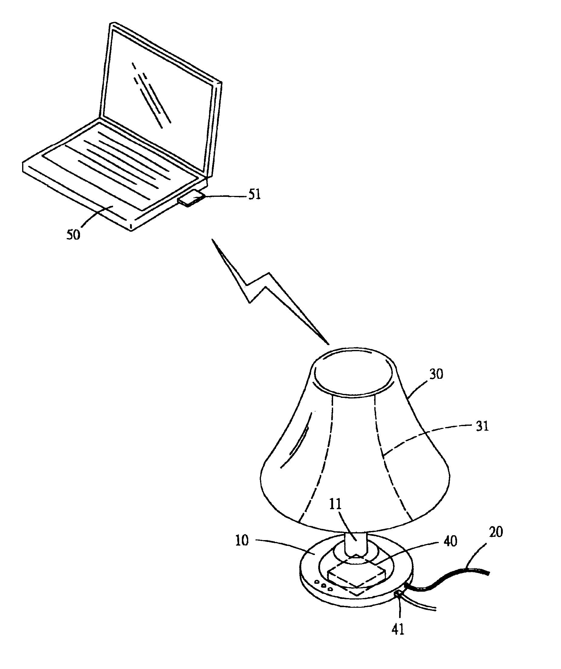
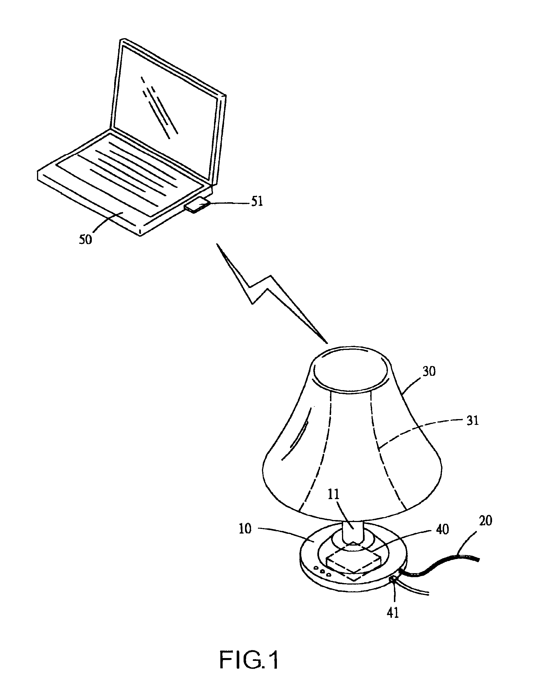
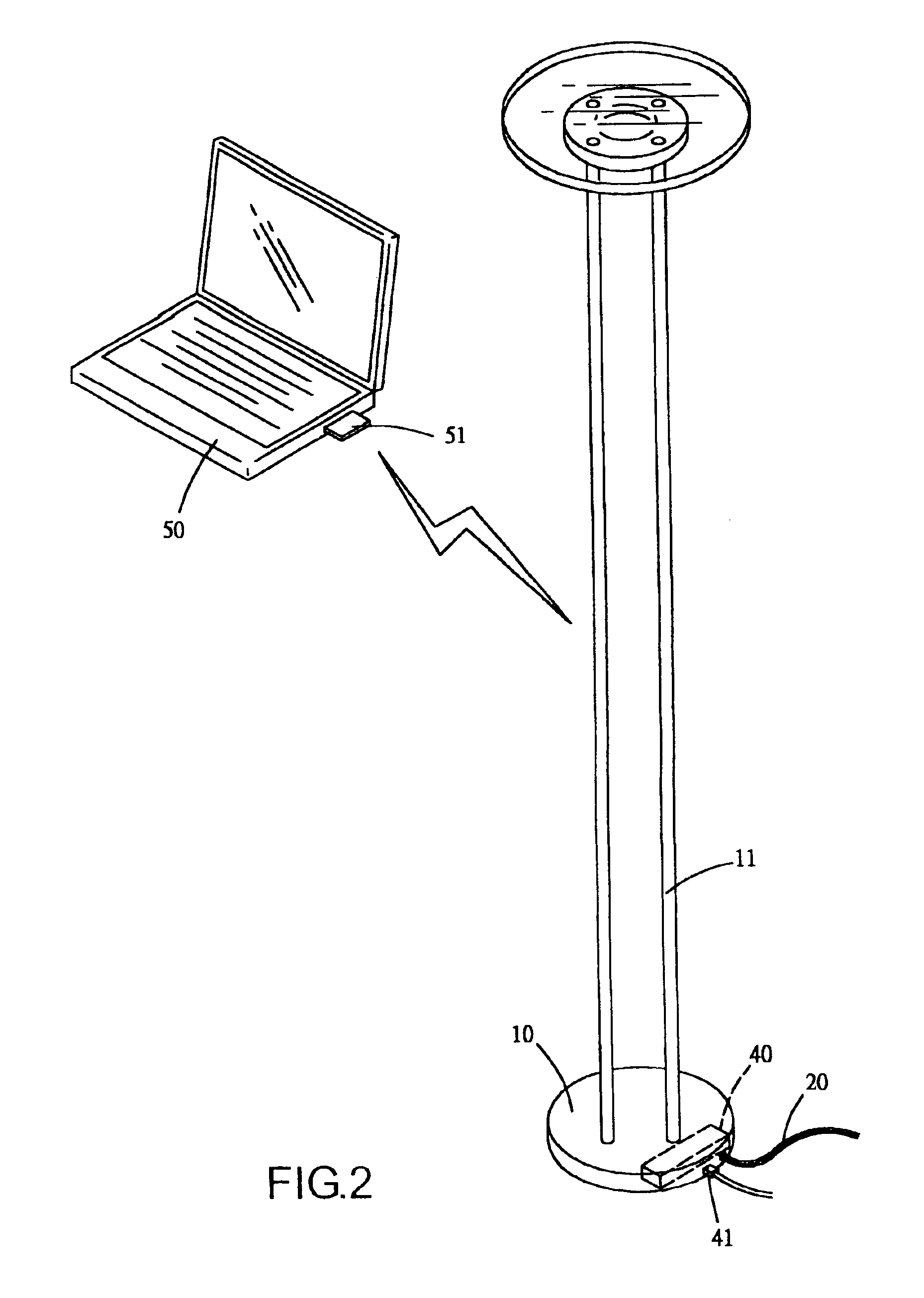
[0014]A basic structure of a lamp according to the present invention is depicted in FIG. 1, comprising a base (10), which constitutes a principle body structure of the lamp. Referring to FIG. 1, which shows one embodiment of the present invention, the lamp is designed to be utilized as a desk lamp and placed on a table top, thus, the base (10) is a base support for the desk lamp, thereby stabilizing the lamp when placed on a table top. A stand (11) is configured to the base (10), and utilized to support a lighting component at an applicable height. A power cable (20) is configured to connect to a light bulb and other lighting components. A metal frame (31) is further configured on the stand (11), and utilized to support a lampshade (30) thereof.

[0015]A wireless transmission component (40) is configured in the base (10), and utilized to implement an electric circuit enabled for wireless signal reception\transmission. The power cable (20) is connected to a power supply circuit of the ...


PUM


Abstract

A lamp, comprising a base of the lamp configured with a wireless transmission component. The wireless transmission component is adapted to having an electric circuit enabled to implement wireless signal reception\transmission. A power cord is connected to a power supply circuit of the electric circuit. An aerial circuit of the electric circuit is connected to a metal stand of the lamp or to a metal frame of a lampshade, therewith enabling a connection to be made between a signal transmission port of the wireless transmission component and wired network equipment. Furthermore, the lamp is structured such to implement wireless signal transmission through linking the wireless transmission component with equipment having a wireless network card.

Description

BACKGROUND OF THE INVENTION[0001](a) Field of the Invention[0002]The present invention relates to lamps, and more particularly to a lamp structured to provide a base platform with functionality for transmitting a wireless signal, enabling the lamp to implement wireless signal transmission to equipment having a wireless network card by means of the lamp and wired network equipment. Furthermore, a metal stand of the lamp or a metal frame of a lampshade can extend extent of reception area of an aerial circuit to a better signal reception position.[0003](b) Description of the Prior Art[0004]In recent years wireless networks have become a topic of hot issue. Network communications technology has gradually moved away from wired type structural frameworks, and through a wireless network everybody can easily acquire instant information by utilizing devices such as a mobile phone, a personal digital assistant, a notebook computer, etc. Therefore, informational electrical appliances are an im...

Claims


Application Information

Patent Timeline
Patent Type & Authority Patents(United States)
IPC IPC(8): H05B37/02H04L12/28H04L12/56H04W52/00H04W88/08
CPCH04W88/08H05B37/0272H04W52/0206H05B47/19Y02D30/70
Inventor HSIAO, PO-SEN
Owner HSIAO PO SEN
Learn More