Aerodynamic base design for TMR reduction

a technology of aerodynamic base and reduction, which is applied in the direction of casings/cabinets/drawers, casings/cabinets/drawers, instruments, etc., can solve the problems of limiting density and unsatisfactory increase in tmr

Inactive Publication Date: 2005-05-10
WESTERN DIGITAL TECH INC
View PDF7 Cites 62 Cited by
  • Summary
  • Abstract
  • Description
  • Claims
  • Application Information

AI Technical Summary

Problems solved by technology

Increased TMR is not desirable because increased TMR limits track-to-track spacing (i.e., track pitch) and consequently limits areal density.

Method used


Image

  • Aerodynamic base design for TMR reduction
  • Aerodynamic base design for TMR reduction
  • Aerodynamic base design for TMR reduction

Examples


Embodiment Construction

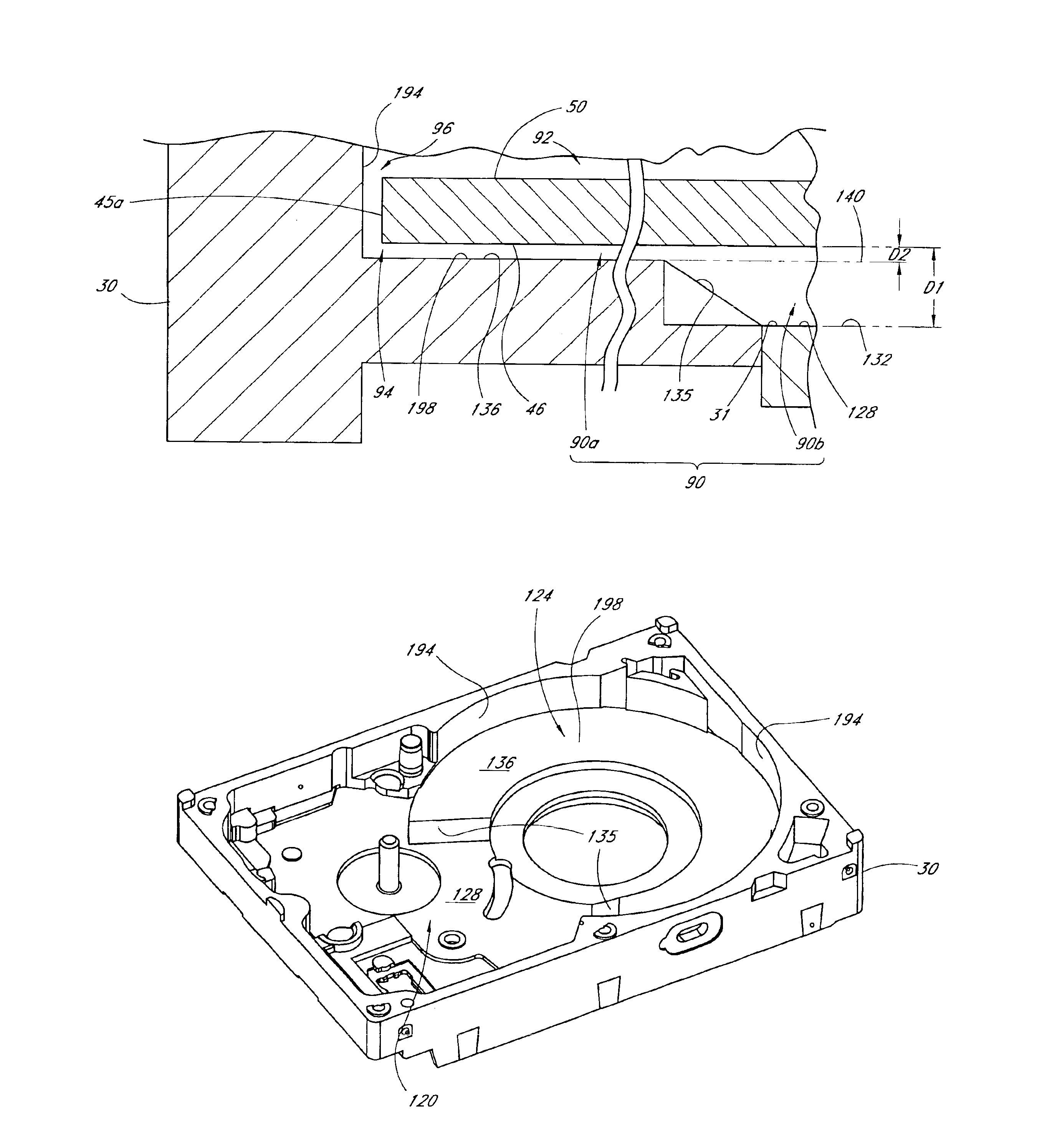
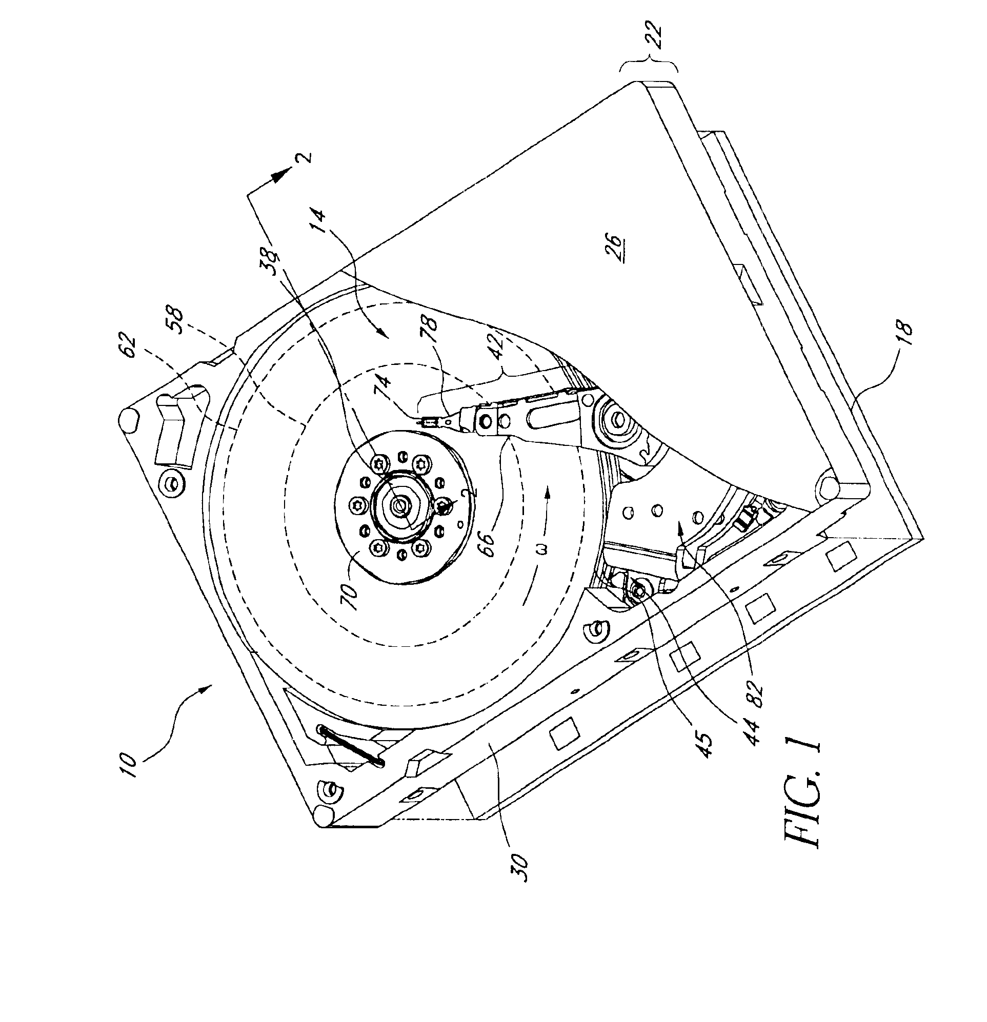
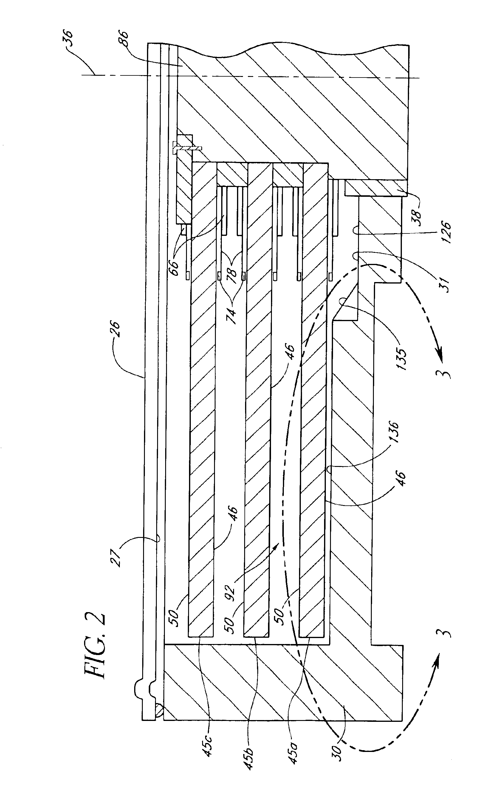
[0021]FIG. 1 is a perspective view of a disk drive 10. The disk drive 10 includes a head-disk assembly (HDA) 14 and a printed circuit board 18. The HDA 14 comprises an enclosure 22 that includes a cover 26 and a base 30. As shown in FIG. 2, the cover 26 has an inner surface 27 that faces the internal components of the disk drive 10 when the disk drive 10 is assembled, and the base 30 has an inner surface 31 that faces the internal components of the disk drive 10 when the disk drive 10 is assembled. The elevation of the inner surface 31 of the base 30 varies in a variety of ways for different embodiments of the invention disclosed herein, as described in more detail below.

[0022]The printed circuit board 18 of the disk drive 10 is connectable to the base 30, but is shown removed therefrom in FIG. 1 for illustration. The HDA 14 also includes a spindle motor assembly 38, a head-stack assembly (HSA) 42, and a disk assembly 44 that includes at least one disk 45. In the illustrated embodim...


PUM

PropertyMeasurementUnit
central angleaaaaaaaaaa
clearance distanceaaaaaaaaaa

Abstract

A disk drive includes an enclosure having a cover and a base, a spindle motor assembly, a disk, and an arcuate raised portion on the base. The disk is mounted on a hub of the spindle motor assembly and has a first surface and a second surface. The first surface is proximate the base and is spaced apart from the base by a first clearance distance. The arcuate raised portion on the base is spaced apart from the disk by a second clearance distance. The second clearance distance is less than the first clearance distance. At least a portion of the disk is superposed over the arcuate raised portion.

Description

BACKGROUND OF THE INVENTION[0001]1. Field of the Invention[0002]This application relates to a disk drive. More particularly, this application relates to a base design that reduces vibration of the disks in the disk drive to improve track-following performance of the disk drive.[0003]2. Description of the Related Art[0004]A disk drive includes at least one disk with a magnetic medium deposited on at least one surface of the disk between an inner circumference and an outer circumference. The disk is mounted on and rotated by a spindle motor assembly, which includes a spindle motor bearing. The disk drive also includes a data transfer head that writes data onto the magnetic medium in concentric, generally circular tracks, and that reads data from the tracks written onto the magnetic medium. In most applications, the data transfer head is extended out over the magnetic medium by an actuator assembly that moves the head in an arcuate path with respect to the surface of the disk that has ...

Claims


Application Information

Patent Timeline
Patent Type & Authority Patents(United States)
IPC IPC(8): G11B33/14G11B25/04
CPCG11B33/148G11B25/043
Inventor OU-YANG, JIN HUIGARBARINO, JONATHAN M.YANG, LIN
Owner WESTERN DIGITAL TECH INC
Why Eureka
Try Eureka