Rotating inflatable device with built-in blower and sensor light

a technology of inflatable devices and sensors, which is applied in the direction of dolls, instruments, packaged goods, etc., can solve the problems of difficult to carry and/or transport the whole assembly, the damage of the inflatable device, and the inability to adjust the balan

Inactive Publication Date: 2005-05-17
WANG HUA CHIANG +1
View PDF1 Cites 25 Cited by
  • Summary
  • Abstract
  • Description
  • Claims
  • Application Information

AI Technical Summary

Benefits of technology

[0004]The present invention relates to a rotating inflatable device which comprises a base with an outlet in a top thereof and an inlet in a side of the base. A blower is received in the base and is driven by the first motor so as to blow air via the outlet. A drive part is received in the base and includes a frame through which a a rotating rod rotatably extends which is driven by a second motor connected to the frame. An output shaft of the second motor is connected to a speed reduction unit located at an underside of the frame. A drum includes an annular ring and a central part which located at a center of the drum by a plurality of ribs connected between the annular ring and the central part. A top end of the rotating rod is co-axially connected to the central part. A balloon has a lower opening thereof mounted to the drum. A central shaft composed of a plurality of sections has its lower end connected to the central part. A top end of the central shaft extends through a top opening of the balloon and is connected to a plate which seals on the top opening of the balloon.
[0005]The present invention will become more obvious from the following description when taken in connection with the accompanying drawings which show, for purposes of illustration only, a preferred embodiment in accordance with the present invention.

Problems solved by technology

Nevertheless, the duct and the blower are exposed so that they tend to be damaged.
The exposed duct makes the whole assembly to be difficult to be carried and / or transported.
The drive wheel and the two idle wheels are exposed so that they could hurt the children playing around the device and dust or even pebbles may enter the gaps between these parts.
Only the drive wheel generates driving force so that the base are applied the force at one side and may have problem of balance.
Some parts of the mast unit are stationary during the operation of the rotating balloon and some are rotated such that friction between these rotating parts and stationary parts results in noise and resistance.

Method used


Image

  • Rotating inflatable device with built-in blower and sensor light
  • Rotating inflatable device with built-in blower and sensor light
  • Rotating inflatable device with built-in blower and sensor light

Examples


Embodiment Construction

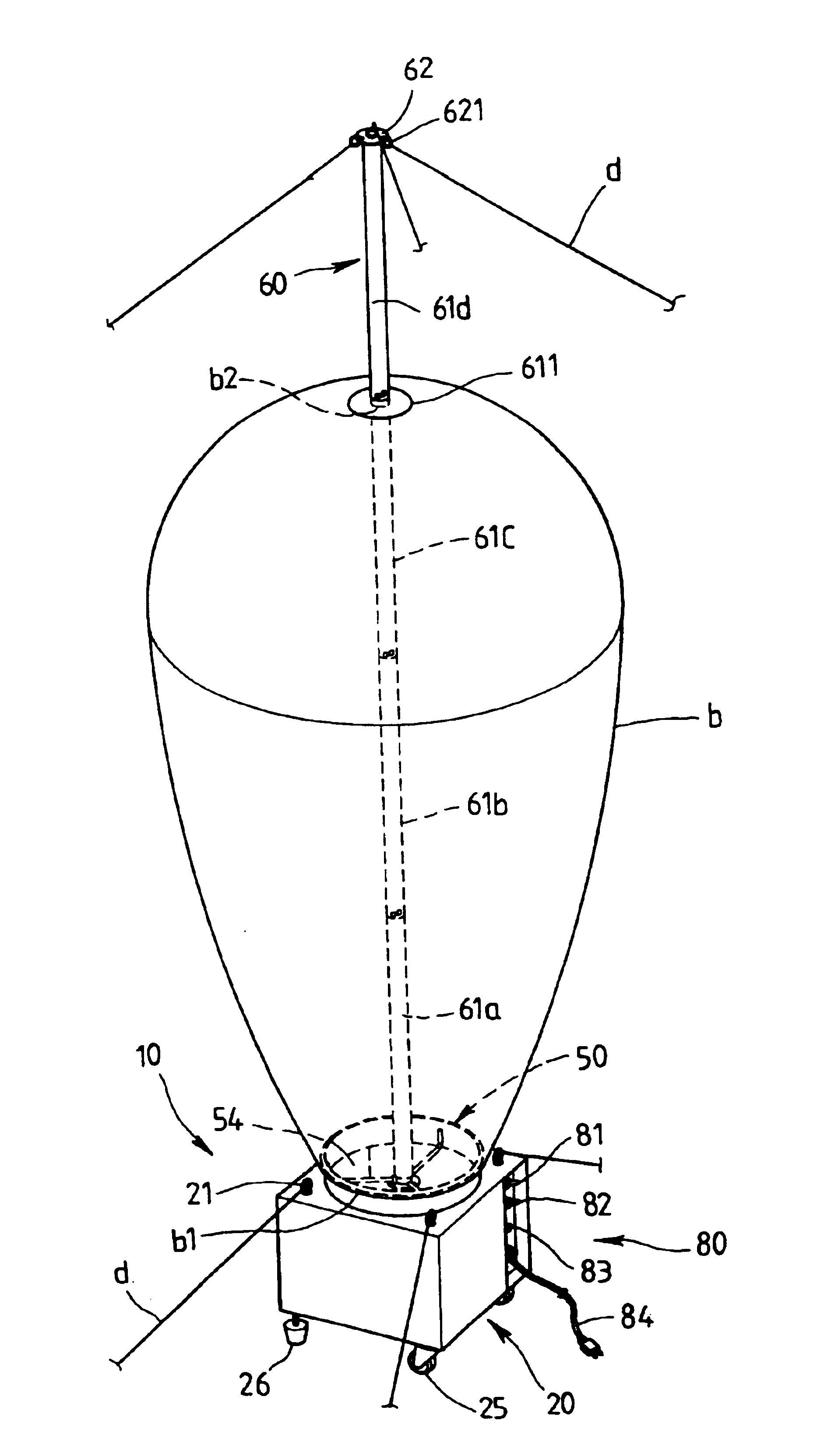
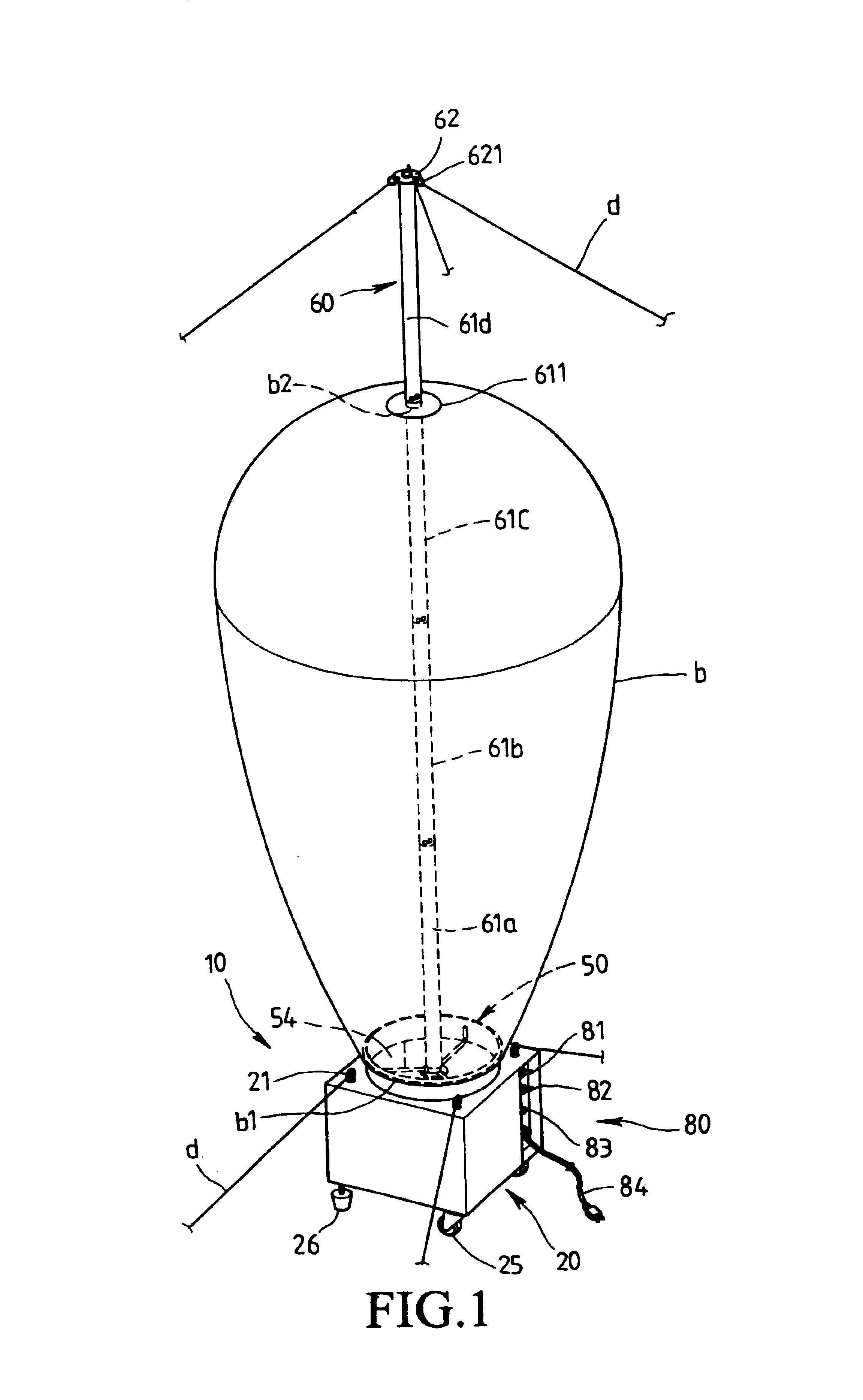
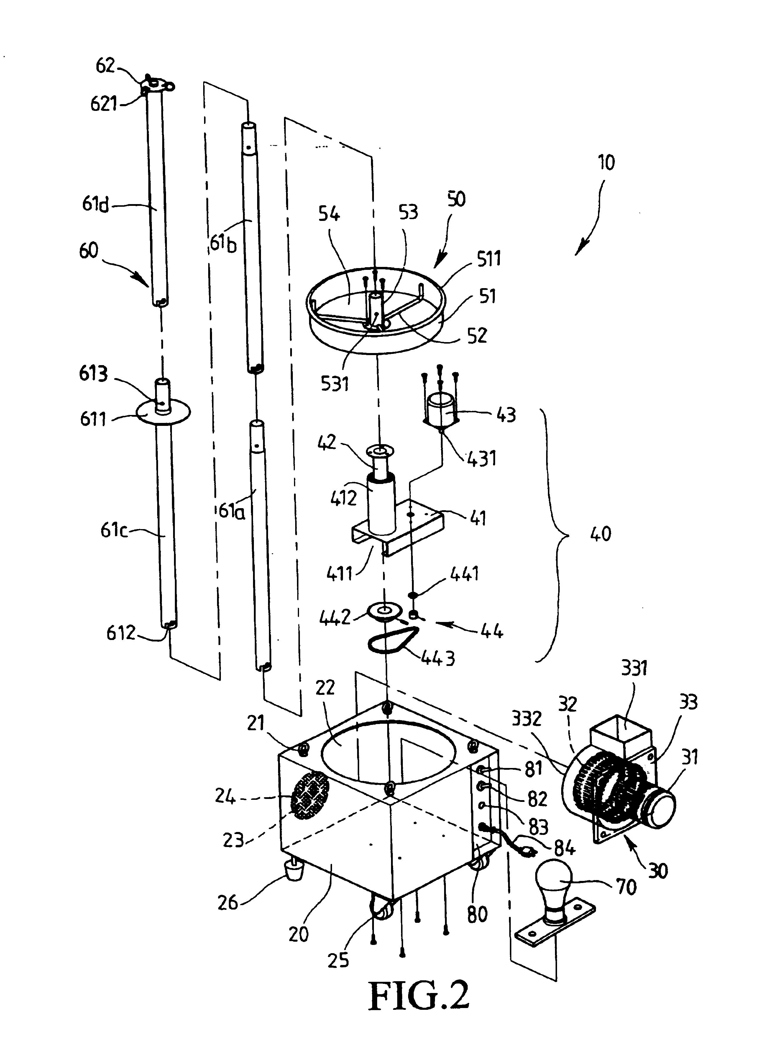
[0014]Referring to FIGS. 1 to 3, the rotating inflatable device 10 of the present invention comprises a box-like base 20 which has an outlet 22 defined in a top thereof and an inlet 23 defined in a side of the base 20. A filter 24 is engaged with the inlet 23 of the base 20. A plurality of rings 21 are located at corners on the top of the base 20 so as to be connected with ropes “d” to fix the base 20. The base 20 further has casters 25 and fixed legs 26 connected to an underside thereof such that the base 20 can be easily moved.

[0015]A blower 30 is received in the base 20 and includes a first motor 31 and a blade part 32 which is driven by the first motor 31. The blade part 32 is received in a wind box 33 and a hole 332 is defined in a front side of the wind box 33 so as to such air into the win box 33. An opening 331 is defined in a top of the wind box 33 and in communication with the outlet 22 of the base 20.

[0016]A drive part 40 is received in the base 20 and includes a frame 41...


PUM

PropertyMeasurementUnit
speedaaaaaaaaaa
driving forceaaaaaaaaaa
forceaaaaaaaaaa

Abstract

A rotating inflatable device includes a base having an outlet a top thereof and an inlet in a side of the base. A blower is received in the base and driven by a motor. A drive part is received in the base and includes a rotating rod which is driven by another motor via a speed reduction unit. A drum to which a lower opening is mounted includes an annular ring and a central part which is located at a center of the drum by a plurality of ribs connected between the annular ring and the central part. A top end of the rotating rod is co-axially connected to the central part. A central shaft composed of a plurality of sections has its a lower end connected to the central part. A top end of the central shaft extends through a top opening of the balloon and is connected to a plate which seals on the top opening of the balloon.

Description

FIELD OF THE INVENTION[0001]The present invention relates to a rotating inflatable device with a built-in blower in a box and the central shaft of the inflatable device is directly connected to the output shaft of the blower so that the inflatable device may rotate in stable condition.BACKGROUND OF THE INVENTION[0002]A conventional rotating balloon apparatus is disclosed in U.S. Pat. No. 6,167,924 and generally includes a blower which is connected to a duct so as to provide air into a base on which the balloon is installed. There are three sets of rotating wheels driven by a motor so as to rotate the lower rotator plate. The bottom of the balloon is secured by the upper and lower rotator plates, and the top of the balloon is positioned by the upper and lower top plates. A mast unit extends through the balloon and is connected to the rotator plates and the top plates so that when the motor rotates, the balloon can be rotated together with the plates. Nevertheless, the duct and the bl...

Claims


Application Information

Patent Timeline
Patent Type & Authority Patents(United States)
IPC IPC(8): A63H27/10A63H27/00G09F15/00G09F19/02
CPCA63H27/10G09F19/02G09F15/0025
Inventor WANG, HUA-CHIANGLIN, HSIN-YEN
Owner WANG HUA CHIANG
Why Eureka
Try Eureka