Rotary bar-projecting mechanism for push-button implement
- Summary
- Abstract
- Description
- Claims
- Application Information
AI Technical Summary
Benefits of technology
Problems solved by technology
Method used
Image
Examples
Example
First Embodiment
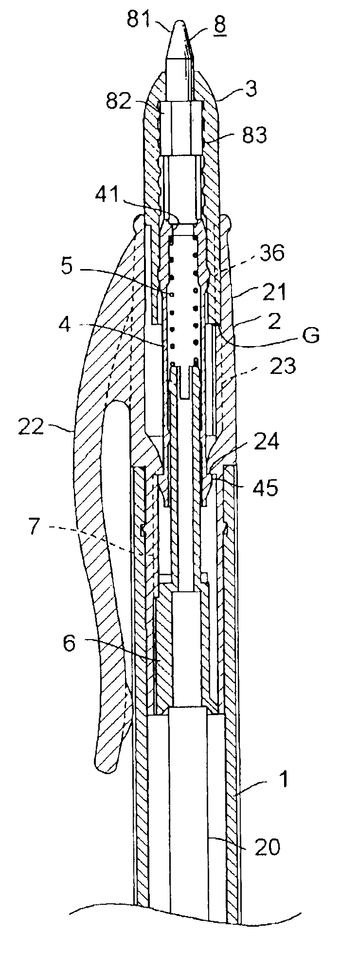
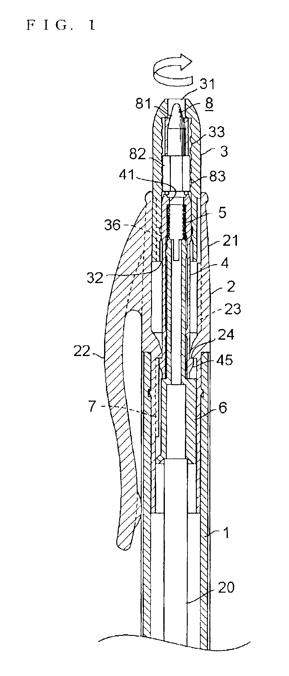
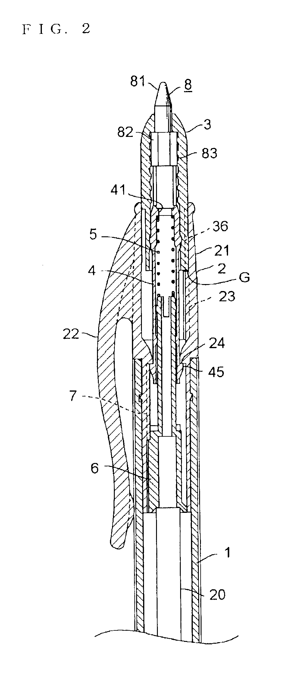
[0031]FIGS. 1 and 2 show a rotary bar-projecting mechanism in a first embodiment according to the present invention included in a push-button writing implement in a state where a bar is held inside and a state where the bar is projected outside, respectively. Referring to FIG. 1, a working member 20, such as a ballpoint refill, is held in a barrel 1 so as to be axially slidable. The working member 20 is pushed backward by a comparatively highly resilient return spring, not shown. A tail cap 2 having a hollow cap body 21 and a clip 22 formed integrally with the cap body 21 is fixedly put on a back part of the barrel 1. A holding means such as a longitudinal counter rib 23 is formed on the inner surface of a back part of the cap body 21, and a holding step 24 is formed on the front side of the counter rib 23.
[0032]Referring to FIGS. 3 to 5 showing the tail cap 2 having the cap body 21 and the clip 22, and provided with the longitudinal counter rib 23 formed on the inne...
Example
Second Embodiment
[0041]FIGS. 11 and 12 show a rotary bar-projecting mechanism in a second embodiment according to the present invention included in a push-button writing implement. In the second embodiment, an external thread 84 formed on a stylus 8 is engaged with an internal thread formed in the inner surface of a back part of a push cam 4 to move the stylus 8 axially. A push button 3 and the stylus 8 are axially movable. The push button 3 is provided on its inner surface with a stopper rib 39 and the stylus 8 is provided with stopper projections 85 to restrain the push button 3 and the stylus 8 from relative turning. A counter rib 23 and the push rib 36 are aligned in a state where a tip part 81 of the stylus 8 is projected outside through a push button 3, and hence the push button 3 is unable to move back ward even if an excessive pressure is applied to the tip part 81 of the stylus 8. Thus, there is no possibility that a cam mechanism operates accidentally even if the push butt...
Example
Third Embodiment
[0042]FIGS. 13 and 14 show a bar-projecting mechanism in a third embodiment according to the present invention included in a push-button writing implement. In the third embodiment, a hole is formed in the bottom of a stylus 8, and a projection formed on a push cam 4 is pressed in the hole of the stylus 8. A push spring 5 inserted in the bore of the push cam 4 is in contact with the back end of a rotary cam 6 to push the rotary cam 6 forward. An external thread 47 formed on the outer surface of a back part of the push cam 4 is engaged with an internal thread 33 formed in the inner surface of a push button 3. The push button 3 is moved axially. The stylus 8 connected to the push cam 0.4 by pressing the projection of the push cam 4 into the hole of the stylus 8 is projected outside from the push button 3 by turning the push button 3.
[0043]The stylus 8 is held in place, and the push button 3 is turned in the direction of the arrow shown in FIG. 13 relative to a tail cap ...
PUM
 Abstract
Description
Claims
Application Information
 - R&D
- Intellectual Property
- Life Sciences
- Materials
- Tech Scout
- Unparalleled Data Quality
- Higher Quality Content
- 60% Fewer Hallucinations
Browse by: Latest US Patents, China's latest patents, Technical Efficacy Thesaurus, Application Domain, Technology Topic, Popular Technical Reports.
© 2025 PatSnap. All rights reserved.Legal|Privacy policy|Modern Slavery Act Transparency Statement|Sitemap|About US| Contact US: help@patsnap.com


