Aircraft brake system

A technology of aircraft and brakes, applied in the direction of aircraft braking arrangements, brakes, aircraft parts, etc., can solve problems such as difficult to accurately control brake pressure

Active Publication Date: 2016-03-16
HONDA PATENTS & TECH NORTH AMERICA
View PDF6 Cites 0 Cited by
  • Summary
  • Abstract
  • Description
  • Claims
  • Application Information

AI Technical Summary

Problems solved by technology

Unfortunately, it can be difficult to precisely control the applied brake pressure and provide proper aircraft deceleration using the control lever

Method used


Image

  • Aircraft brake system
  • Aircraft brake system
  • Aircraft brake system

Examples


Embodiment Construction

[0031] The description and drawings herein are exemplary only and various modifications and changes may be made in the disclosed structures without departing from the scope of the appended claims. The various identified components of the hydraulic systems and emergency / parking brake systems disclosed herein are technical terms only and may vary from manufacturer to manufacturer. These terms should not be taken as limiting the invention or the appended claims. The drawings are shown for the purpose of illustrating one or more exemplary embodiments, and are not intended to limit the claims that follow. Unless otherwise indicated, all references to directions and positions refer to the orientation of the components as shown in the drawings and are not to be construed as limitations on the appended claims.

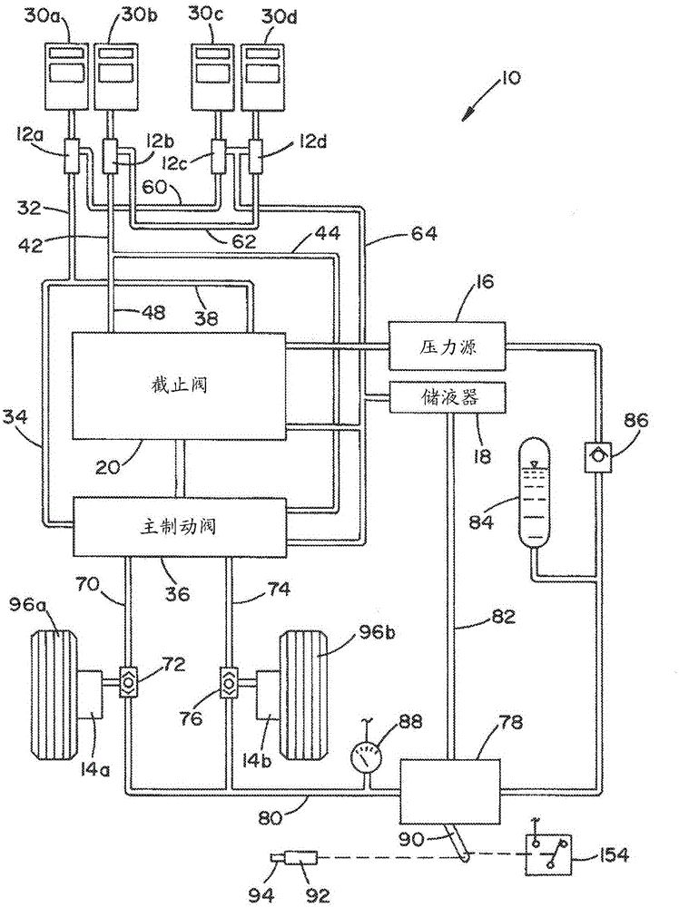
[0032] Now see attached picture, figure 1 A hydraulic system 10 of an aircraft is schematically depicted. Hydraulic system 10 includes master cylinders and, in the depicted...


PUM


Abstract

An aircraft emergency brake system includes a modulating emergency / parking brake valve in fluid communication with and disposed between a pressure source and a wheel brake and a lever assembly operatively connected with the brake valve. The emergency brake system is operative in first and second stages. The lever assembly includes a handle, a lock mechanism and an unlock mechanism. The handle is movable between a non-actuated position and a fully-actuated position. The brake pressure provided to the wheel brake through the brake valve depends on a position of the handle. The lock mechanism is operatively connected with the handle to obstruct the handle from moving from the first stage to the second stage. The unlock mechanism is disposed on the handle to unlock the lock mechanism allowing movement of the handle to the second stage position from the first stage position.

Description

Background technique [0001] Many types of aircraft, including small business jets, use a dynamic braking system as the primary braking device for the aircraft. In order to solve the unexpected failure of the dynamic braking system, a non-dynamic redundant braking system is usually provided. One such redundant braking system includes a modulating emergency / parking brake valve in combination with an accumulator powerplant. The brake valve may direct pressurized fluid (eg, hydraulic or brake fluid, compressed air, etc.) from an accumulator to apply braking of the aircraft in the event of a failure of the primary braking system. In addition to providing emergency braking, the brake valve fully engages the brakes for extended periods of parking. [0002] Typically, a lever or other actuated mechanism in the cockpit is mechanically connected to the brake valves to control the flow of pressurized fluid in the aircraft's hydraulic system to and from the brake cylinders at the wheels...

Claims


Application Information

Patent Timeline
Patent Type & Authority Applications(China)
IPC IPC(8): B60T8/42
CPCB64C25/001B64C25/44B60T7/101B60T11/046B60T13/662
Inventor C·T·奥康奈尔尾山博树
Owner HONDA PATENTS & TECH NORTH AMERICA
Why Eureka
Try Eureka