Pressurizer device

a pressure device and pressure technology, applied in the field of orthopaedics, can solve the problems of disassembly and assembly of cement, and achieve the effect of reducing the number of pressure points

Inactive Publication Date: 2005-05-17
REVIE IAN +1
View PDF17 Cites 37 Cited by
  • Summary
  • Abstract
  • Description
  • Claims
  • Application Information

AI Technical Summary

Problems solved by technology

Known pressurizer devices are either removed prior to stem introduction or a part of the pressurizer is removed or changed to a separate component thereby disturbing the cement and the pressure generation.

Method used


Image

  • Pressurizer device
  • Pressurizer device
  • Pressurizer device

Examples


Embodiment Construction

[0035]Embodiments of the present invention and the advantages thereof are best understood by referring to the following descriptions and drawings, wherein like numerals are used for like and corresponding parts of the drawings.

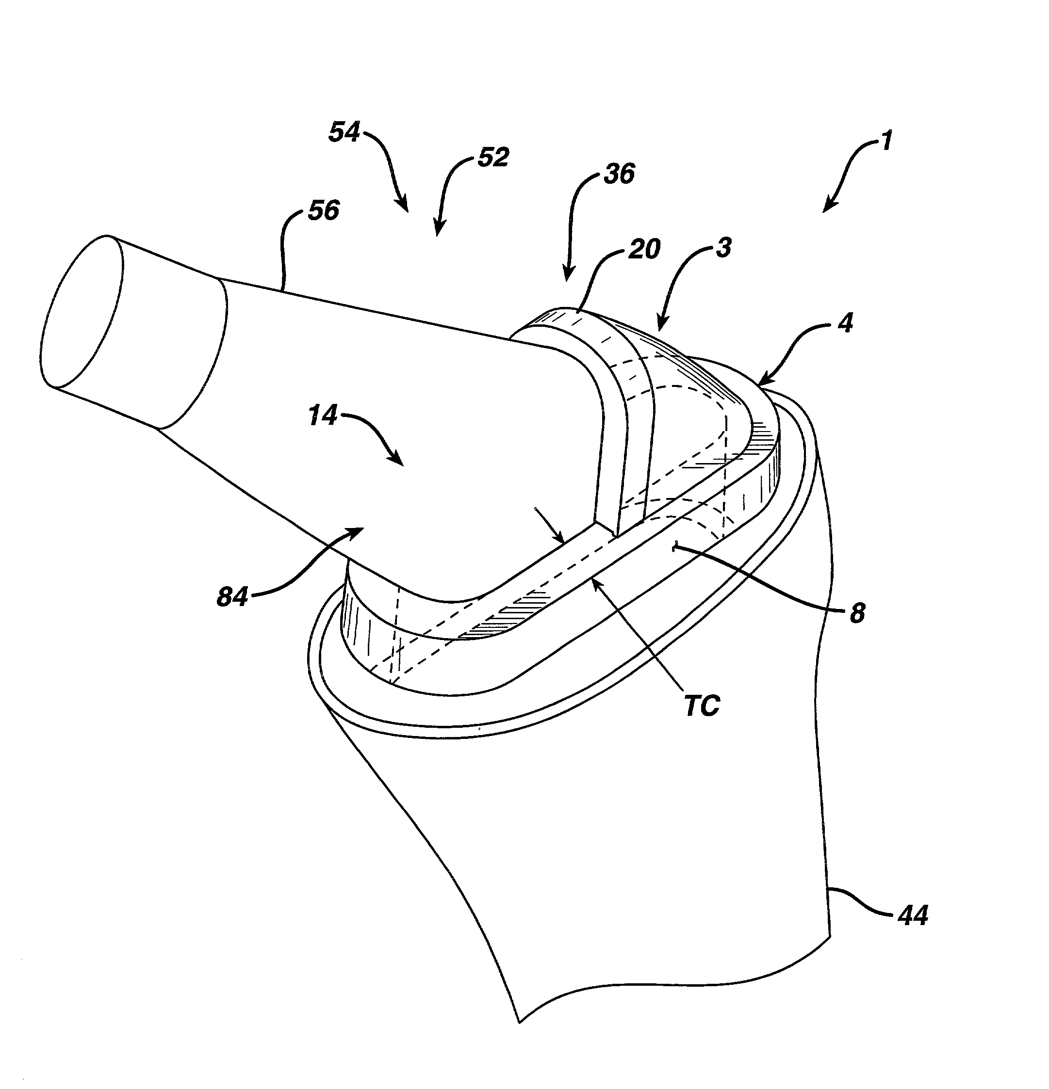
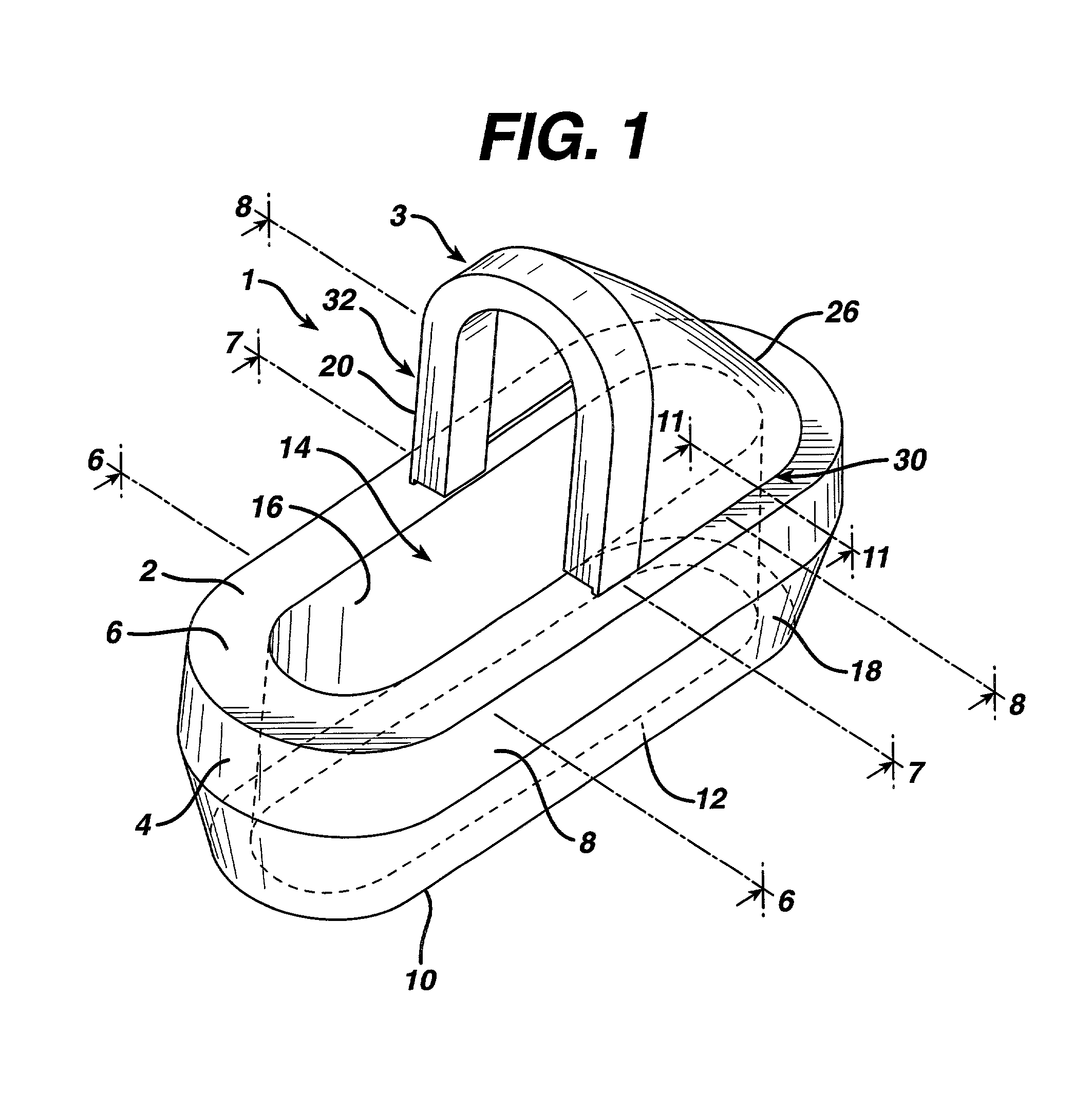
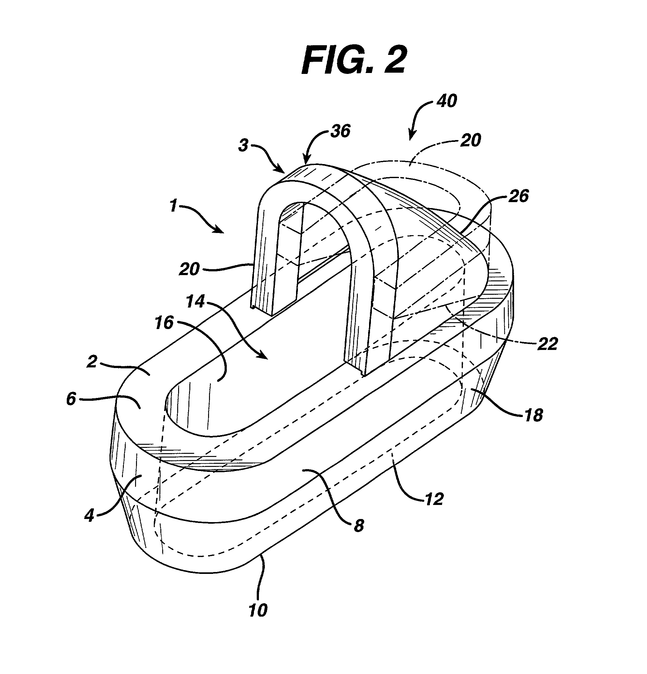
[0036]According to the present invention and referring now to FIG. 1, a pressurizer device 1 is provided. The pressurizer device 1 is formed in two parts. A collar 4 and a hood 3. The collar 4 and the hood 3 are preferably made of a suitable, durable and flexible material. For example, the collar 4 may be formed of a silicone, for example, a medical grade silicone. Likewise, the hood 3 may be formed of a silicone, for example a medical grade silicone. While the pressurizer device 1 may be made by any suitable manufacturing techniques, preferably the collar 4 and the hood 3 of the pressurizer device 1 may be integrally molded in an injection molding machine and made from a medical grade silicone.

[0037]Preferably and as shown in FIG. 1, the body 2 of the pressur...


PUM


Abstract

A pressurizer device (1) is provided for maintaining pressure in the cement in a bone cavity during introduction of a prosthetic component, for example, a replacement hip stem. The pressurizer device (1) has a collar (4) and a hood (3). The hood (3) has a hoop (20) which arches across the central opening (14) of the collar (4). The hood (3) can be provided with or without a lining.

Description

CROSS REFERENCE TO RELATED APPLIACTIONS[0001]This application is a Continuation-in-Part of U.S. patent application Ser. No. 09 / 385,669 filed Aug. 27, 1999, now abandoned, entitled PRESSURIZER DEVICE.TECHNICAL FIELD OF THE INVENTION[0002]The present invention relates generally to the field of orthopaedics, and more particularly to a pressurizer device for use in cemented femoral hip stem replacement. The pressurizer device is also suitable for use in other cemented prosthetic applications.BACKGROUND OF THE INVENTION[0003]This invention relates to implantable articles and methods for manufacturing such articles. More particularly, the invention relates to bone prosthesis and process for manufacturing the same.[0004]There are known to exist many designs for and methods for manufacturing implantable articles, such as bone prostheses. Such bone prostheses include components of artificial joints, such as elbows, hips, knees and shoulders.[0005]A femoral bone is prepared for replacement hi...

Claims


Application Information

Patent Timeline
Patent Type & Authority Patents(United States)
IPC IPC(8): A61F2/46A61F2/00A61F2/30A61F2/38A61F2/36A61F2/40
CPCA61B17/8808A61F2250/0036A61F2/367A61F2/3859A61F2/389A61F2002/30014A61F2002/30018A61F2002/30126A61F2002/30131A61F2002/30228A61F2002/30324A61F2002/30528A61F2002/30561A61F2002/30571A61F2002/30777A61F2002/30957A61F2002/3625A61F2002/4062A61F2220/0025A61F2230/0008A61F2230/0013A61F2230/0069A61F2250/0018A61F2250/0029A61B17/8811
Inventor REVIE, IANNAYBOUR, JOHN
Owner REVIE IAN
Why Eureka
Try Eureka