
Log positioning and conveying apparatus

Inactive Publication Date: 2005-05-24
SAVICO LTEE +1
View PDF19 Cites 24 Cited by
  • Summary
  • Abstract
  • Description
  • Claims
  • Application Information

AI Technical Summary

Benefits of technology

[0025]c) at least one log position monitoring scanner each capable of scanning a plane intersecting said log channel upstream of a corresponding one of said rollers, each said at least one monitoring scanner being operatively connected to said control center for forwarding real-time log position data concerning the position of a log;
[0026]In one embodiment, said log processing system further com

Problems solved by technology

However, some problems exist in the existing systems.
Firstly, the entire geometry of the log is not computed, and consequently, the log-scan of the front face of the log is not necessarily representative of the entire length of the often longitudinally irregular log.
Thus, even if the log is rotated to obtain an optimized log position according to the front face of the log, the overall yield from the log may not be optimal.
Also, although a certain optimal log position is computed and the log turning apparatus is controlled to rotate the log according to the desired position, the effective real position of the log may not be exactly as desired, since the log may react in an unforeseen manner while it is rotated, and it may accidentally be positioned differently from the computed optimal position.

Method used


Image

  • Log positioning and conveying apparatus
  • Log positioning and conveying apparatus
  • Log positioning and conveying apparatus

Examples


Embodiment Construction

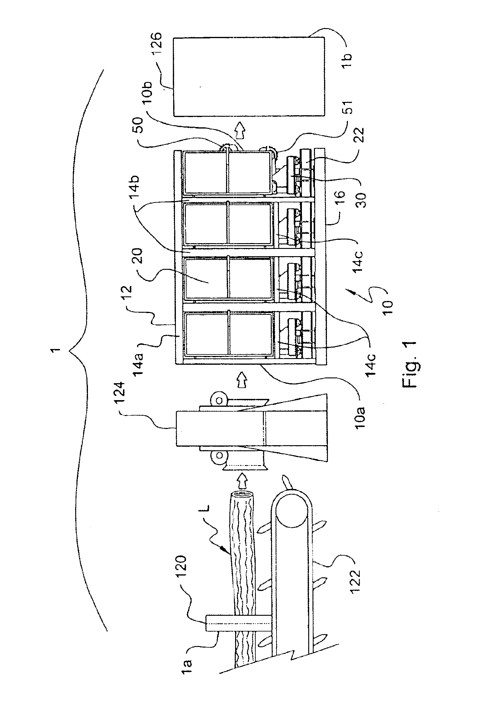
[0038]With reference to FIG. 1, there is shown a log processing system 1 comprising a log conveyor 122 of known construction with a log-shape scanner 120 mounted thereon, a log turning apparatus 124 of known construction, a log positioning and conveying apparatus 10 according to the present invention, and a sawing apparatus 126 of known construction. Log-processing system 1 is used for conveying a log L from an upstream end 1a defined immediately upstream of log-shape scanner 120, to a downstream end 1b defined immediately downstream of sawing apparatus 126, the log being properly positioned and cut while it is being conveyed by system 1, as described hereinafter.

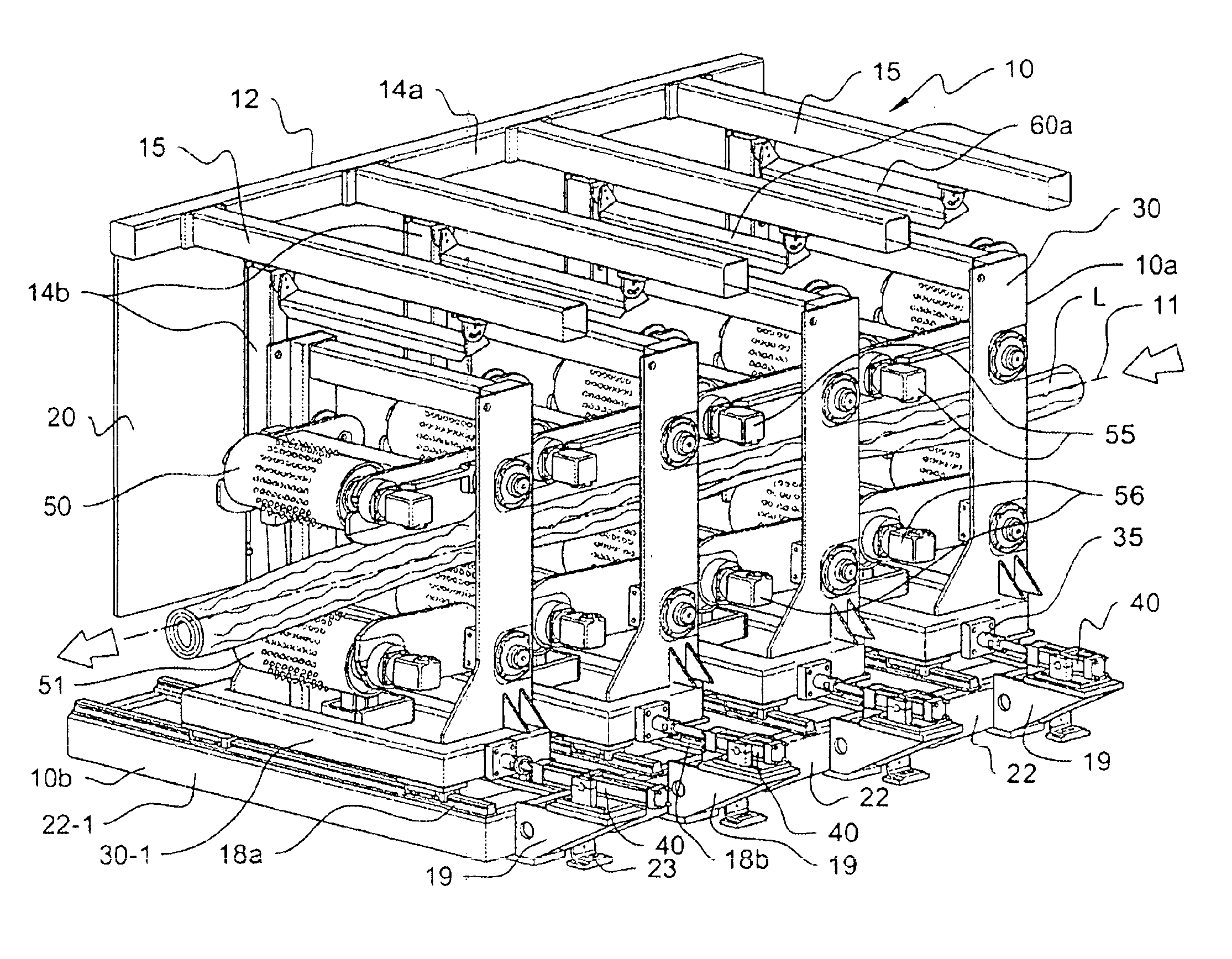
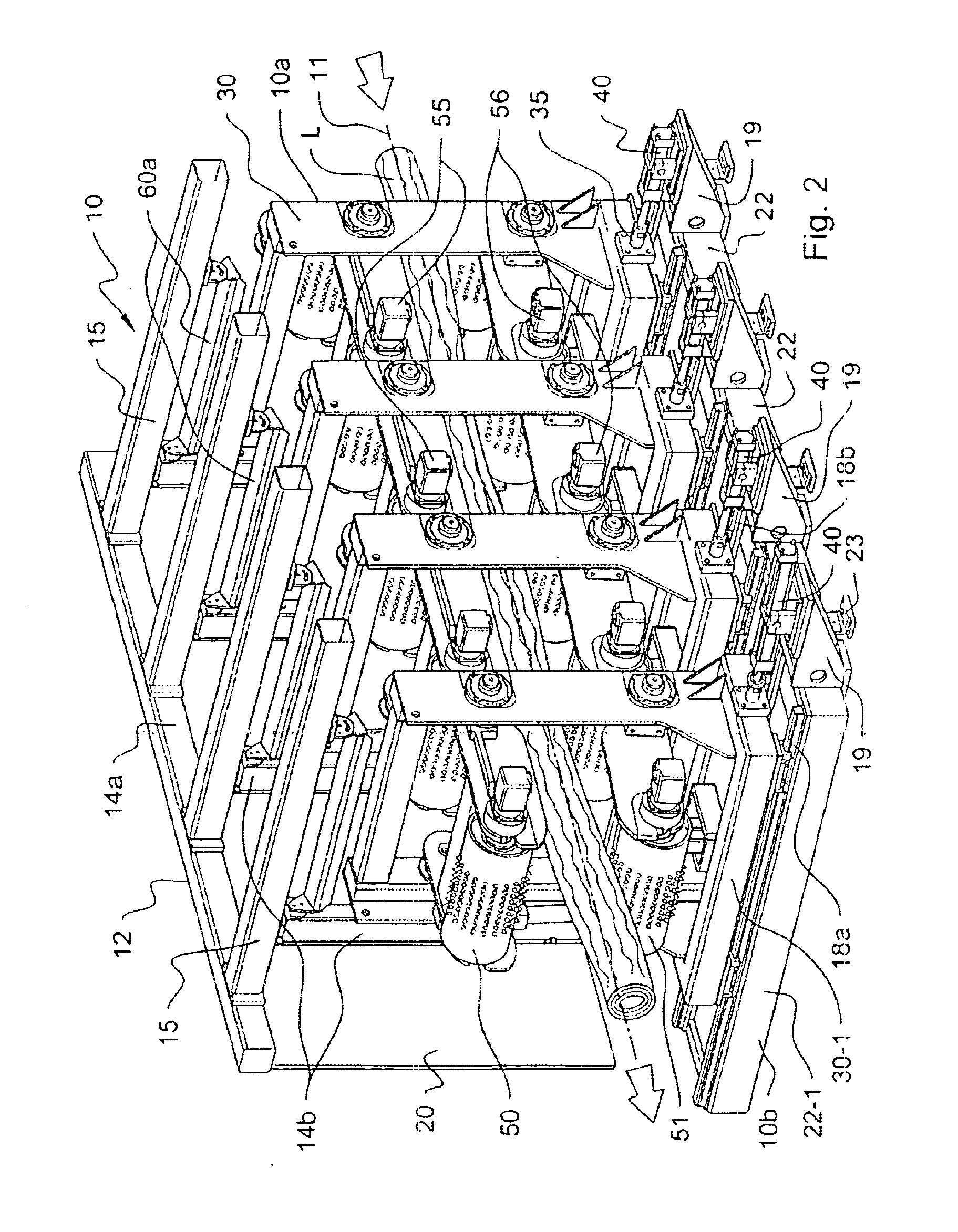
[0039]As shown in appended FIGS. 1-7, log conveying and sawing apparatus 10 comprises an open frame 12, rollers 50, 51, lateral actuators 40, arm-pivoting actuators 44, 45, roller rotation-inducing motors 55, 56, and log-position monitoring devices 60a, 60b. Apparatus 10 further defines an upstream end 10a and a downstream ...


PUM


Abstract

The log positioning and conveying apparatus is used for conveying a log from an upstream end to a downstream end, and for positioning a log according to a predetermined downstream position. The apparatus comprises an open frame and a number of powered conveying rollers arranged therein in a row. These rollers, in addition to being rotatable, are displaceable in two directions relative to the open frame, namely, in a vertical direction for correcting the position of the log vertically relative to the open frame, and in a horizontal direction transversal to the longitudinal axis of the conveying apparatus, for correcting the position of the log transversely relative to the longitudinal axis.

Description

FIELD OF THE INVENTION[0001]The present invention relates to log conveyors for feeding logs to a chip-and-saw apparatus, and more particularly to a log positioning conveyor capable of adjusting the position of the log.BACKGROUND OF THE INVENTION[0002]For environmental and economical reasons, it is essential to maximize the production of lumber from each log. To achieve the best possible wood yield from a log, the log has to be suitably positioned in relation to the stationary sawing members of a sawing apparatus in which the log is fed, both with respect to the angular position of the log about its longitudinal axis and the orientation and position of the longitudinal axis of the log.[0003]Modern log-positioning machines are computer-assisted. It is known to scan the front face of the log with an optical scanner, and to subsequently analyze the log image by means of a computer program. The computer can command a log turning apparatus to adjust the angular position of the log about i...

Claims


Application Information

Patent Timeline
IPC IPC(8): B23Q1/25B23Q1/62B23Q7/14B23Q7/05B27B31/06B27B31/00
CPCB23Q1/621B23Q7/055B27B31/06B27B31/003B23Q7/14
Inventor ACHARD, RENEGAUTHIER, ROBERTPERREAULT, JEAN-PIERRESTE-CROIX, EDDY
Owner SAVICO LTEE
Learn More