Stud-supported storage assembly

a storage assembly and stud technology, applied in the field of pivoting shelves, can solve the problem of not disclosing a new stud-supported storage assembly, and achieve the effect of saving room space, convenient and convenient setting up and us

Inactive Publication Date: 2005-05-24
JAEGER LINDA
View PDF12 Cites 4 Cited by
  • Summary
  • Abstract
  • Description
  • Claims
  • Application Information

AI Technical Summary

Benefits of technology

[0012]Still yet another object of the present invention is to provide a new stud-supported storage assembly that is easy and convenient to set up and use.
[0013]Even still another object of the present invention is to provide a new stud-supported storage assembly that conserves room space by having shelves which fold between the elongate stud members.

Problems solved by technology

While these devices fulfill their respective, particular objectives and requirements, the aforementioned patents do not disclose a new stud-supported storage assembly.

Method used


Image

  • Stud-supported storage assembly
  • Stud-supported storage assembly
  • Stud-supported storage assembly

Examples


Embodiment Construction

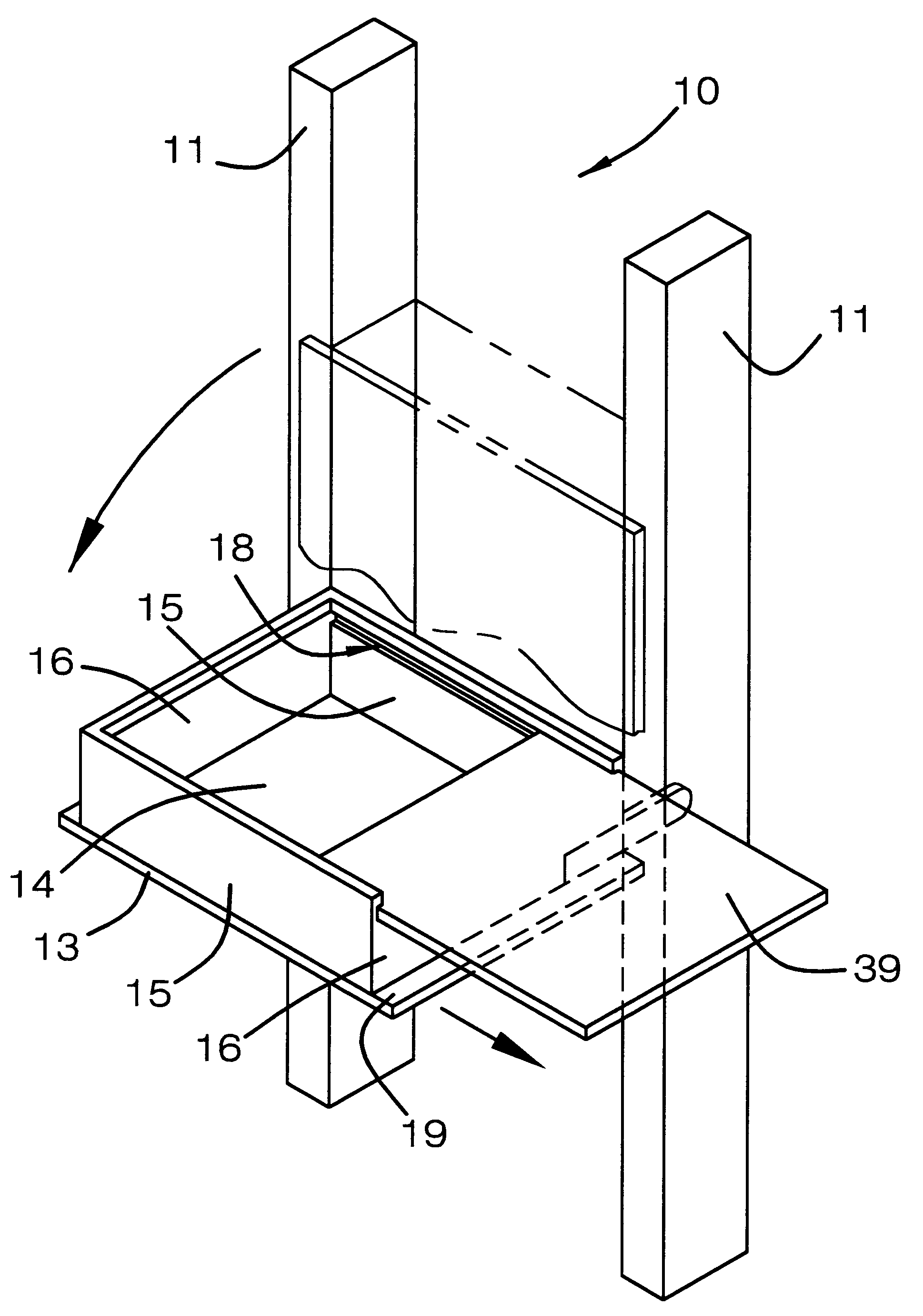
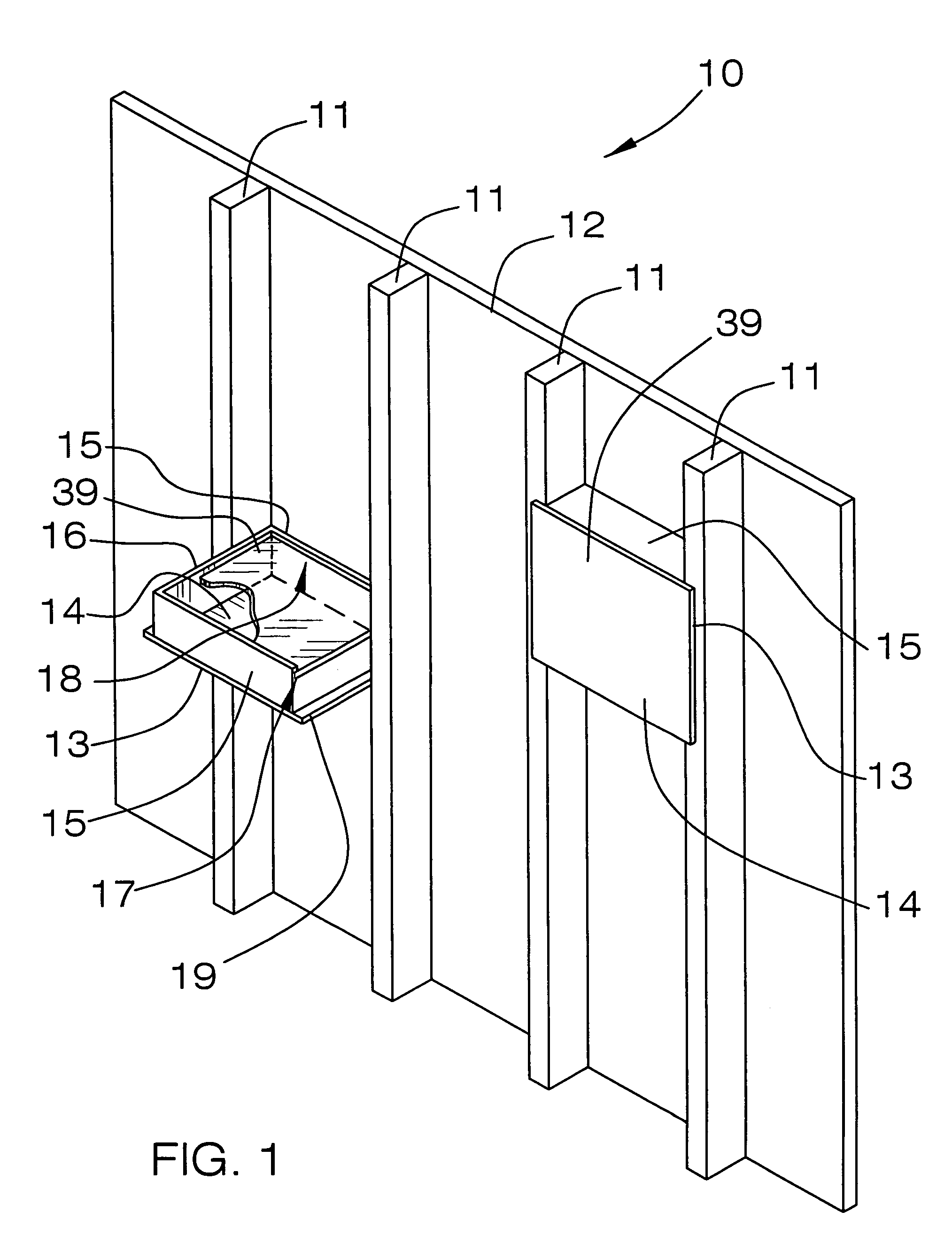
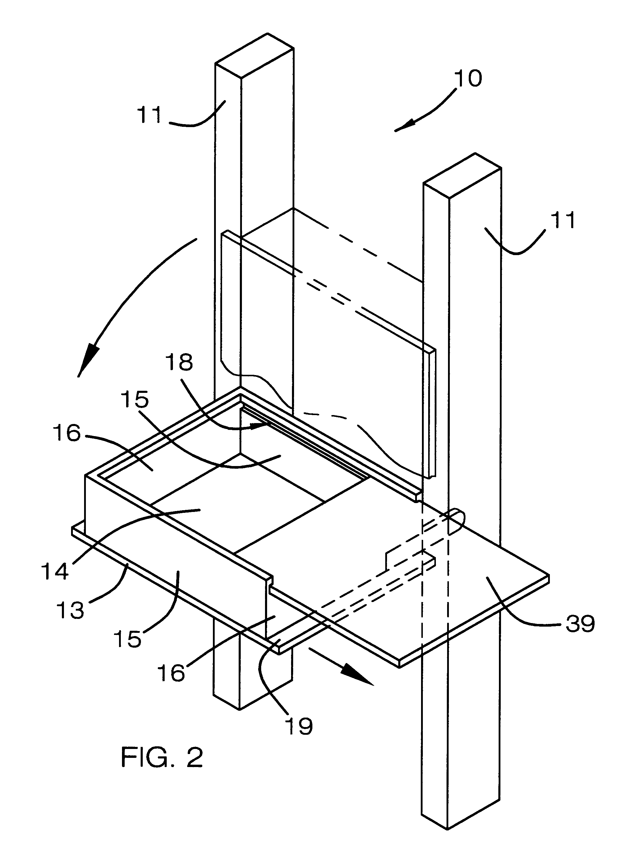
[0020]With reference now to the drawings, and in particular to FIGS. 1 through 4 thereof, a new stud-supported storage assembly embodying the principles and concepts of the present invention and generally designated by the reference numeral 10 will be described.

[0021]As best illustrated in FIGS. 1 through 4, the stud-supported storage assembly 10 generally comprises a support assembly including elongate stud members 11 being spaced apart, and also including a wall member 12 being conventionally attached to the elongate stud members 11.

[0022]A shelf assembly includes a shelf member 13 being hingedly attached to the support assembly and having bottom, side, and end walls 14–16 and an open top. The shelf member 13 also includes a cover 39 being removably disposed upon the open top of the shelf member 13. Each of the side walls 15 has a groove 17,18 being disposed in an interior side thereof and extending a length of the side wall 15. The cover 39 is received in the grooves 17,18 of the...


PUM


Abstract

A stud-supported storage assembly for providing addition storage space upon a wall member. The stud-supported storage assembly includes a support assembly including elongate stud members being spaced apart, and also including a wall member being attached to the elongate stud members; and also includes a shelf assembly including a shelf member being hingedly attached to the support assembly and having bottom, side, and end walls and an open top; and further includes a shelf mounting assembly for hingedly mounting the shelf member to the support assembly.

Description

BACKGROUND OF THE INVENTION[0001]1. Field of the Invention[0002]The present invention relates to pivotal shelves and more particularly pertains to a new stud-supported storage assembly for providing addition storage space upon a wall member.[0003]2. Description of the Prior Art[0004]The use of pivotal shelves is known in the prior art. More specifically, pivotal shelves heretofore devised and utilized are known to consist basically of familiar, expected and obvious structural configurations, notwithstanding the myriad of designs encompassed by the crowded prior art which have been developed for the fulfillment of countless objectives and requirements.[0005]Known prior art includes U.S. Pat. No. 2,166,430; U.S. Pat. No. 1,707,013; U.S. Pat. No. 5,368,378; U.S. Pat. No. 5,882,094; U.S. Pat. No. 5,819,958; U.S. Pat. No. 5,577,819; and U.S. Pat. No. Des. 333,238. [0006]While these devices fulfill their respective, particular objectives and requirements, the aforementioned patents do not...

Claims


Application Information

Patent Timeline
Patent Type & Authority Patents(United States)
IPC IPC(8): A47B46/00A47B81/00
CPCA47B81/005A47B46/005E04F19/08
Inventor JAEGER, LINDA
Owner JAEGER LINDA
Why Eureka
Try Eureka