Pump and conduit sterilizing system

a technology of pump and conduit, which is applied in the direction of cleaning using liquids, swimming pools, physical therapy, etc., can solve the problem of not disclosing the new pump and conduit sterilizing system, and achieve the effect of preventing the backflow of cleaning solution and being convenient to set up and us

Inactive Publication Date: 2005-12-27
STRAWBRIDGE JOSEPH M
View PDF16 Cites 3 Cited by
  • Summary
  • Abstract
  • Description
  • Claims
  • Application Information

AI Technical Summary

Benefits of technology

[0012]Still yet another object of the present invention is to provide a new pump and conduit sterilizing system that is easy and convenient to set up and use.
[0013]Even still another object of the present invention is to provide a new pump and conduit sterilizing system that prevents the backflow of cleaning solution into the spa and swimming pool.

Problems solved by technology

While these devices fulfill their respective, particular objectives and requirements, the aforementioned patents do not disclose a new pump and conduit sterilizing system.

Method used


Image

  • Pump and conduit sterilizing system
  • Pump and conduit sterilizing system
  • Pump and conduit sterilizing system

Examples


second embodiment

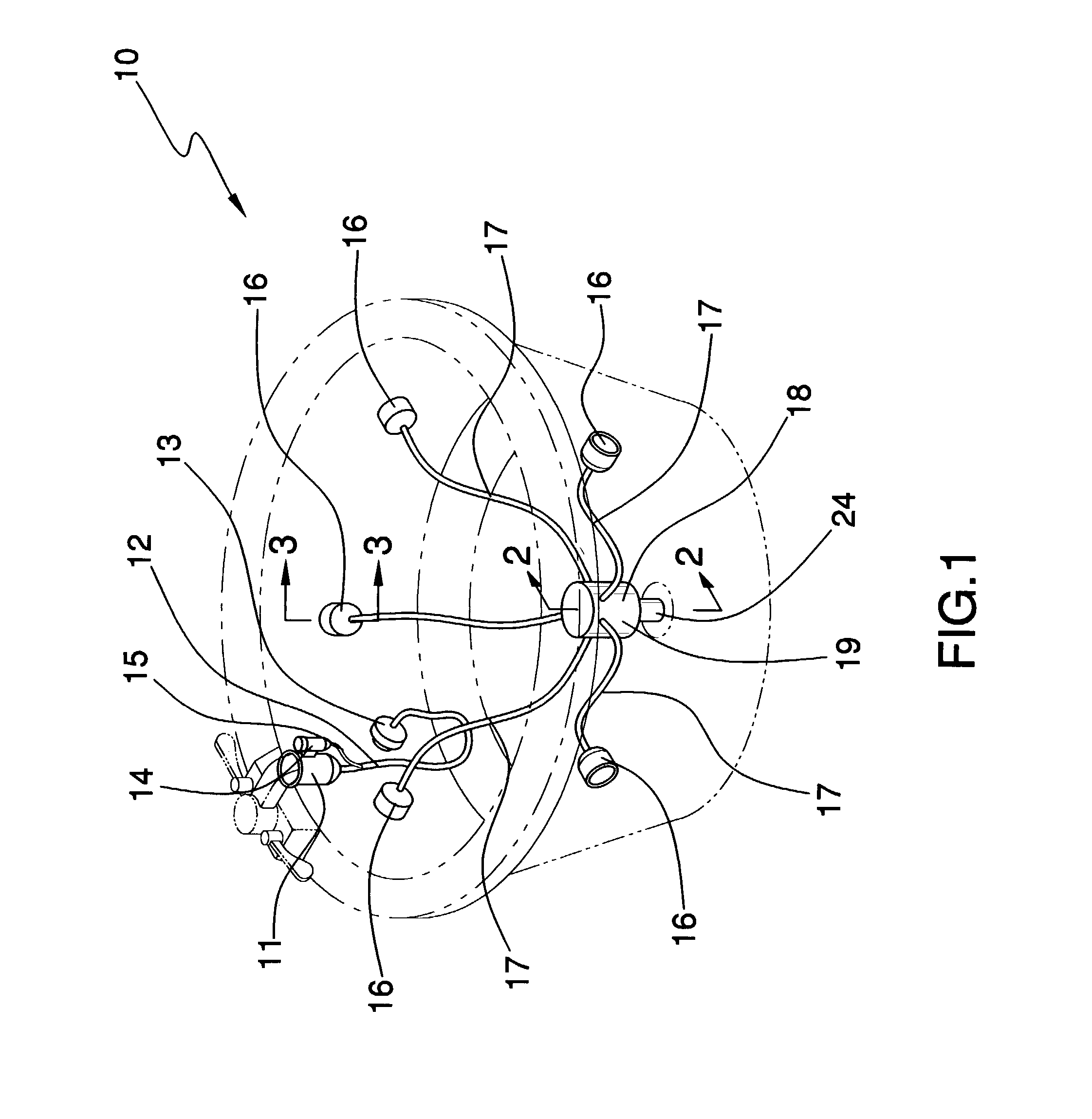
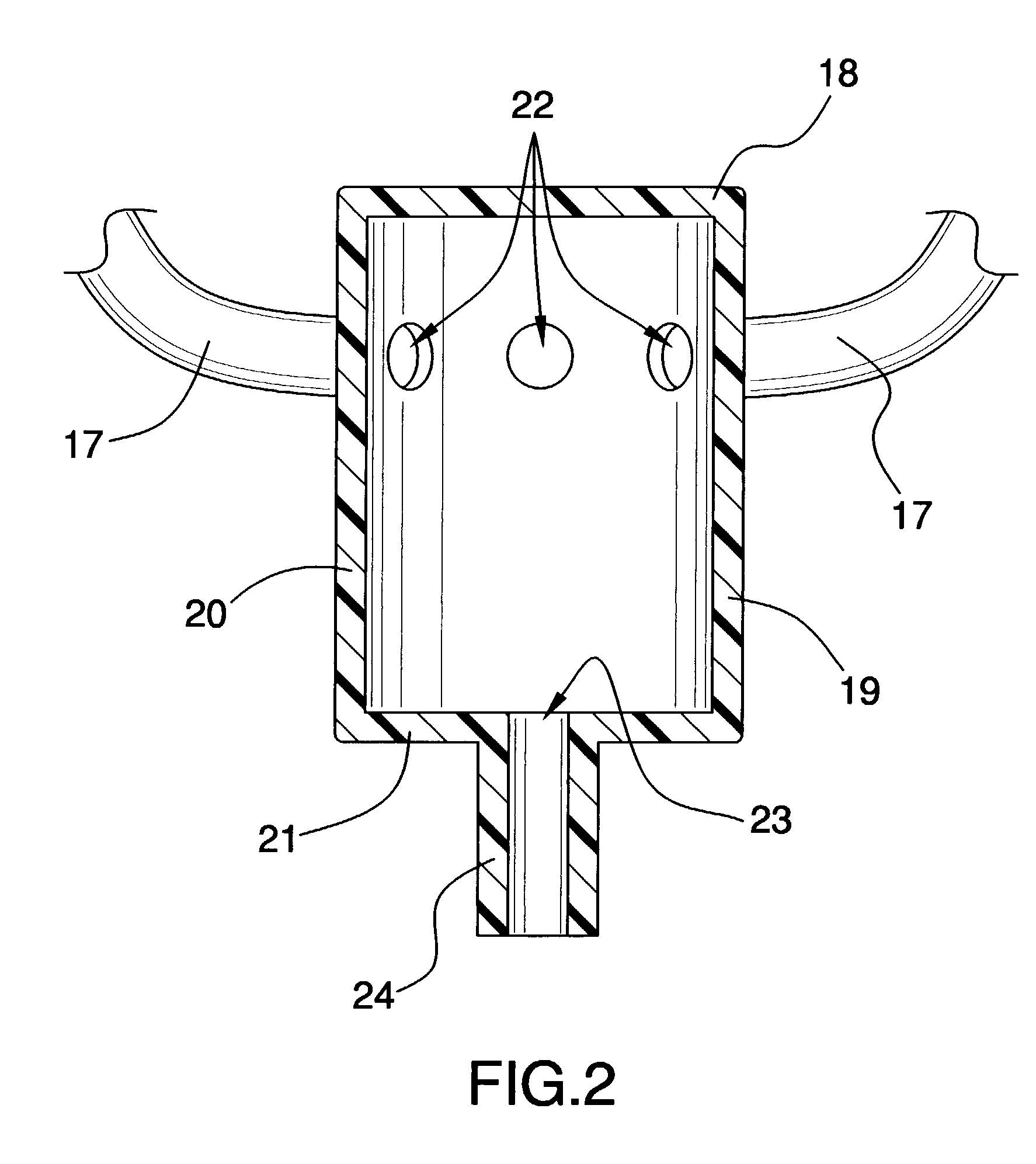
[0029]As a second embodiment, the drainage manifold 18 also includes a plurality of spigots 25 being conventionally attached over the holes 22 of the container 19 and extending outwardly therefrom, and further having valve members 26 being conventionally disposed in the spigots 25, and further includes a tubular drainage fitting 24 being conventionally attached over the drainage opening 23 and extending outwardly from the bottom wall 21 of the container 19 and being adapted to fasten to a drainage hose and having a bore being disposed therethrough. The outtake hoses 16 are conventionally attachable to the spigots 25. The drainage manifold 18 also includes a bracket 27 being conventionally attached to an outer side of the side wall 20 of the container 19 and being adapted to hang upon a side wall of the spa and the swimming pool.

third embodiment

[0030]As a third embodiment, the drainage manifold 18 also includes a suction cup member 28 being conventionally attached to an end of the tubular drainage fitting 24 and being adapted to being suctioned upon a wall of the spa and swimming pool.

[0031]One or more jet plug members 29 are adapted to be removably attached about selected liquid-forced jets. Each of the one or more jet plug members 29 includes a cap portion 30 being adapted to securely fit about a selected liquid-forced jet and having node portions conventionally protruding outwardly from a side wall of the cap portion 30 for locking the cap portion 30 about the selected liquid-forced jet, and also includes a handle portion 31 for manipulating the cap portion 30. Fasteners are fastenable about the jet plug members 29. Each fastener includes a tie member 34 having a plurality of holes 36 being disposed along a portion thereof and also includes a T-shaped handle member 37 being conventionally attached to the tie member 34 a...


PUM

PropertyMeasurementUnit
perimeteraaaaaaaaaa
sizeaaaaaaaaaa

Abstract

A pump and conduit sterilizing system for cleaning out and sterilizing the pump and the conduits attached to the pump for spas and swimming pools and the like. The pump and conduit sterilizing system includes a pliable spigot fitting member being adapted to attach to a spigot for a spa and a swimming pool; and also includes an intake hose being connected to the pliable spigot fitting member; and further includes an intake jet fitting member being adapted to attach to a selected liquid-forced jet; and also includes a cleaning solution assembly being connected to the intake hose and including a reservoir being adapted to hold cleaning solution therein, and also including a tubular member being attached to the reservoir and to the intake hose; and further includes a jet drainage assembly including a plurality of outtake jet fitting members being adapted to be attached to selected liquid-forced jets, and also including outtake hoses being attached to the outtake jet fitting members, and further including a drainage manifold being attached to the outtake hoses; and further including one or more jet plug members being adapted to be removably attached about selected liquid-forced jets.

Description

BACKGROUND OF THE INVENTION[0001]1. Field of the Invention[0002]The present invention relates to pump and conduit sterilizing systems and more particularly pertains to a new pump and conduit sterilizing system for cleaning out and sterilizing the pump and the conduits attached to the pump for spas and swimming pools and the like.[0003]2. Description of the Prior Art[0004]The use of pump and conduit sterilizing systems is known in the prior art. More specifically, pump and conduit sterilizing systems heretofore devised and utilized are known to consist basically of familiar, expected and obvious structural configurations, notwithstanding the myriad of designs encompassed by the crowded prior art which have been developed for the fulfillment of countless objectives and requirements.[0005]Known prior art includes U.S. Pat. No. 5,682,628; U.S. Pat. No. 5,545,335; U.S. Pat. No. 5,381,566; U.S. Pat. No. 4,859,345; U.S. Pat. No. 4,676,894; and U.S. Pat. No. Des. 349,949.[0006]While these d...

Claims


Application Information

Patent Timeline
Patent Type & Authority Patents(United States)
IPC IPC(8): A61H33/00A61L2/18B08B3/04C02F1/50
CPCA61L2/18A61H2033/0016C02F1/50C02F2103/42
Inventor STRAWBRIDGE, JOSEPH M.
Owner STRAWBRIDGE JOSEPH M
Why Eureka
Try Eureka