Multi-band antenna

a multi-band antenna and antenna technology, applied in the field of antennas, can solve the problems of increasing the complexity and the cost of the antenna, and the bandwidth of the conventional dual-band pifa antenna is not wide enough to cover the total bandwidth of 802.11a and 802.11b

Inactive Publication Date: 2005-05-24
HON HAI PRECISION IND CO LTD
View PDF7 Cites 82 Cited by
  • Summary
  • Abstract
  • Description
  • Claims
  • Application Information

AI Technical Summary

Benefits of technology

[0011]A multi-band antenna in accordance with the present invention for an electronic device includes a ground patch, a first radiating patch, a second radiating patch, a connecting patch connecting the first and second radiating patches with the ground patch, and a feeder cable. The multi-band antenna further comprises an insulative planar base, and the ground patch, the first radiating patch, the second radiating patch and the connecting patc

Problems solved by technology

However, the bandwidth of the conventional dual-band PIFA antenna is not wide enough to cover the total bandwidth of 802.11a and 802.11b.
Though this antenna can achieve wider bandwidth by adjusting the param

Method used


Image

  • Multi-band antenna
  • Multi-band antenna
  • Multi-band antenna

Examples


Embodiment Construction

[0022]Reference will now be made in detail to a preferred embodiment of the present invention.

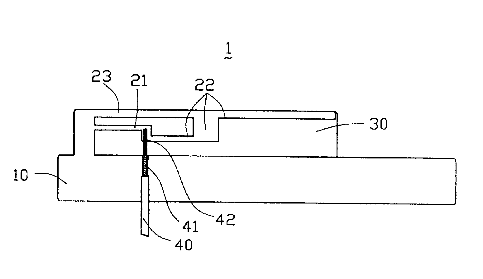
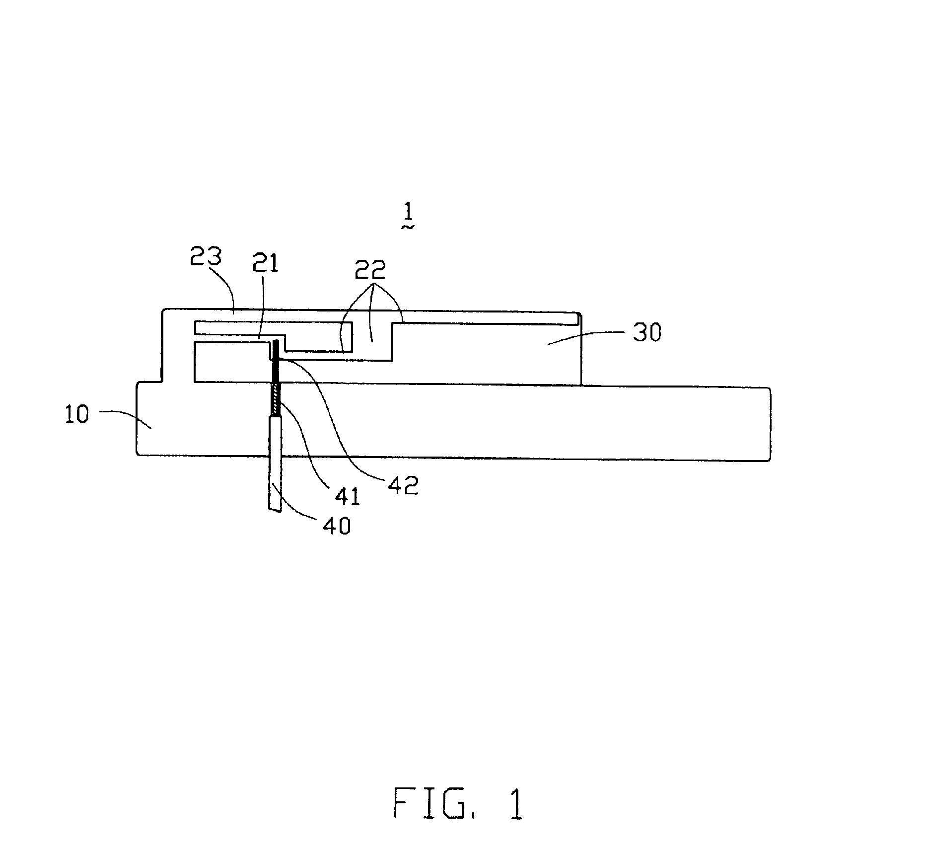
[0023]Referring to FIG. 1, a multi-band antenna 1 in accordance with a preferred embodiment of the present invention comprises an insulative planar base 30, a ground patch 10, a first radiating patch 21, a second radiating patch 22, a connecting patch 23 and a signal feeder cable 40.

[0024]The ground patch 10, the first radiating patch 21, the second radiating patch 22 and the connecting patch 23 are made from conductive sheet metal, are arranged on a same surface of the insulative planar base 30, and electrically connect with one another. The connecting patch 23 connects at a first end to the ground patch 10, at a medial portion to a first end of the first radiating patch 21, and at a second end to a medial portion of the second radiating patch 22. A second end of the first radiating patch 21 connects with a first end of the second radiating patch 22, and a second end of the second radiatin...


PUM


Abstract

A multi-band antenna (1) includes a ground patch (10), a first radiating patch (21), a second radiating patch (22), a connecting patch (23) connecting the first and second radiating patches with the ground patch, and a feeder cable (40). The ground patch, the connecting patch, the second radiating patch and the feeder cable form a planar inverted-F antenna (PIFA), and the first radiating patch, the connecting patch, the ground patch and the feeder cable form a loop antenna.

Description

CROSS-REFERENCE TO RELATED APPLICATIONS[0001]This present application is related to a other two patent applications commonly entitled “MULTI-BAND ANTENNA”, invented by the same inventors, and assigned to a common assignee.BACKGROUND OF THE INVENTION[0002]1. Field of the Invention[0003]The present invention relates to an antenna, and in particular to a multi-band antenna employed in a mobile electronic device.[0004]2. Description of the Prior Art[0005]In 1999, the wireless local area network (WLAN) market saw the introduction of the 2.4 GHz IEEE 802.11b standard. Today 802.11b and IEEE 802.11a are among several technologies competing for market leadership and dominance.[0006]The wireless 802.11a standard for WLAN runs in the 5 GHz spectrum, from 5.15-5.825 GHz. 802.11a utilizes the 300 MHz of bandwidth in the 5 GHz Unlicensed National Information Infrastructure (U-NII) band. Although the lower 200 MHz is physically contiguous, the Federal Communications Commission (FCC) has divided t...

Claims


Application Information

Patent Timeline
IPC IPC(8): H01Q9/04H01Q1/24
CPCH01Q9/0421H01Q1/243
Inventor DAI, HSIN KUOTAI, LUNG SHENGLIN, HSIEN-CHUKUO, CHIA-MING
Owner HON HAI PRECISION IND CO LTD
Why Eureka
Try Eureka