Multi-band antenna with broadband function

a broadband function and multi-band antenna technology, applied in the direction of antennas, antenna details, electrically short antennas, etc., can solve the problems of affecting the antenna design of the system supplier and consumer, inconvenient operation at high frequencies, and trouble for system suppliers and consumers, so as to achieve the effect of convenient operation

Inactive Publication Date: 2007-07-26
ADVANCED CONNECTEK INC
View PDF16 Cites 22 Cited by
  • Summary
  • Abstract
  • Description
  • Claims
  • Application Information

AI Technical Summary

Benefits of technology

[0016]Besides, the connecting plate of the first conductive arm is connected to the ground near the first end, and the connecting plate of the second conductive arm is connected to the ground near the second end. The two connecting arms are thus farther from each other. Therefore, it is easier to perform the operations of bending the conductive arms and soldering the feed wire.

Problems solved by technology

However, this phenomenon causes troubles and inconvenience for the system suppliers and consumers.
Among all difficulties, the antenna is still the key factor in the wireless communications designs.
This affects their antenna designs.
The first connecting part A2 and the second connecting part B2 are too close to each other, and inconvenient for operations at high frequencies.
Moreover, since the first conductive plate A1 and the second conductive plate B1 extend respectively from the first connecting part A2 and the second connecting part B2 toward the same direction, bending the first radiating part A and the second radiating part B is difficult when fabricating the antenna.
It is also difficult to connect a feed wire to the first conductive plate A1 by soldering.

Method used


Image

  • Multi-band antenna with broadband function
  • Multi-band antenna with broadband function
  • Multi-band antenna with broadband function

Examples


first embodiment

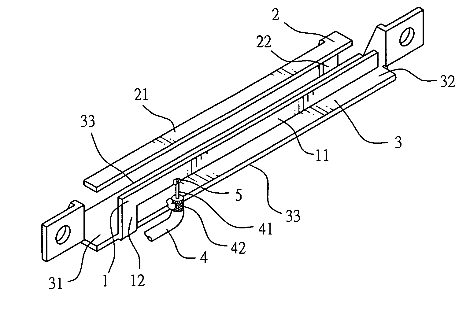
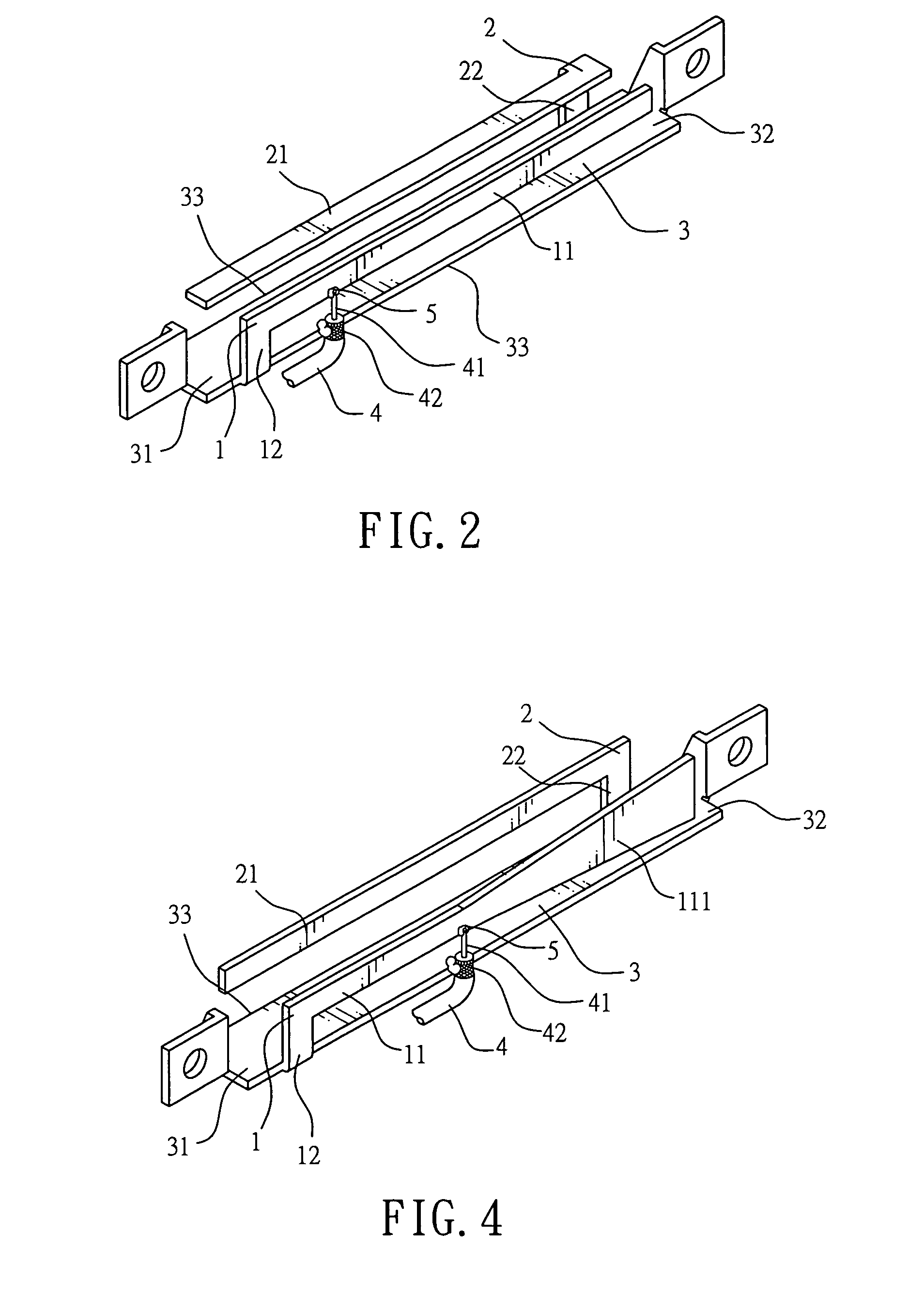
[0022]the invention is illustrated in FIG. 2. The multi-band antenna comprises a first conductive arm 1, a second conductive arm 2, a ground 3, and a feed wire 4. The ground 3 has a first end 31, a second end 32, and two elongated sides 33 connected with the first end 31 and the second end 32. Each of the first conductive arm 1 and the second conductive arm 2 further comprises a radiating plate 11, 21 and a connecting plate 12, 22. The connecting plate 12 of the first conductive arm 1 is connected to one of the elongated sides 33 of the ground 3 and is adjacent to the first end 31. The connecting plate 22 of the second conductive arm 2 is connected to the other elongated side 33 of the ground 3 and is adjacent to the second end 32. The radiating plate 11 of the first conductive arm 1 extends from the connecting plate 12 toward the second end 32. The radiating plate 21 of the second conductive arm 2 extends from the connecting plate 22 toward the first end 31. The radiating plate 11 ...

second embodiment

[0025]With reference to FIG. 4, the multi-band antenna comprises a first conductive arm 1, a second conductive arm 2, a ground 3, and a feed wire 4. The ground 3 has a first end 31, a second end 32, and two elongated sides 33 connected with the first end 31 and the second end 32. Each of the first conductive arm 1 and the second conductive arm 2 further comprises a radiating plate 11, 21 and a connecting plate 12, 22. The connecting plate 12 of the first conductive arm 1 is connected to one of the elongated sides 33 of the ground 3 near the first end 31. The connecting plate 22 of the second conductive arm 2 is connected to the other elongated side 33 of the ground 3 near the second end 32. The radiating plate 11 of the first conductive arm 1 extends from the connecting plate 12 toward the second end 32. The radiating plate 21 of the second conductive arm 2 extends from the connecting plate 22 toward the first end 31. In this embodiment, a coaxial cable 4 comprising a central wire 4...


PUM


Abstract

A multi-band antenna with the broadband function is based upon a planar inverted-F antenna with two conductive arms and a ground. The two conductive arms extend from the ground near the two opposite ends of the ground. Two radiation plates of the two conductive arms extend toward each other. The multi-band antenna has a sufficient large band at high frequencies. Since the conductive arms are disposed close to the two ends of the ground, operations of bending the two conductive arms or soldering a feed wires are simpler and have a higher yield.

Description

BACKGROUND OF THE INVENTION[0001]1. Field of the Invention[0002]The invention relates to a multi-band antenna with a broadband function and, in particular, to a multi-band antenna based upon a planar inverted-F antenna (PIFA) and having two conductive arms disposed at both ends of a ground, wherein the radiation plates of the conductive arms extend toward each other.[0003]2. Description of Related Art[0004]Personal mobile communications have great potential and business opportunities in the wireless communication industry. During their evolution, many systems adopting different techniques and channels have been developed. Therefore, they play important roles in different areas and markets. However, this phenomenon causes troubles and inconvenience for the system suppliers and consumers. One consequential point is that different systems, e.g., GSM900, DCS1800, and PCS1900, use different frequency bands.[0005]For the convenience of users, manufacturers have spent a lot of manpower to ...

Claims


Application Information

Patent Timeline
Patent Type & Authority Applications(United States)
IPC IPC(8): H01Q1/38H01Q5/25H01Q5/378
CPCH01Q1/243H01Q5/378H01Q5/25H01Q9/0421
Inventor CHUNG, MING-HSUNCHIU, TSUNG-WENTSENG, CHING-FENGBAI, YUN-FANCHEN, AN-CHIAHSIAO, FU-REN
Owner ADVANCED CONNECTEK INC
Why Eureka
Try Eureka