Rotating optical joint

a technology of rotating optical joints and optical joints, applied in the field of rotating optical joints, can solve the problems of only a single transmission channel, limited bandwidth of such joints, wear and tear of parts,

Inactive Publication Date: 2005-05-24
AIR PRECISION
View PDF9 Cites 26 Cited by
  • Summary
  • Abstract
  • Description
  • Claims
  • Application Information

AI Technical Summary

Benefits of technology

[0026]The particularly simple arrangement defined above allows bidirectional transmission of optical signals, whilst leaving the central part of the joint totally free, when necessary. Thus, the first and second organs can easily be hollow along the said common axis, when required by the application.

Problems solved by technology

Among these disadvantages one must mention notably the wear and tear of the parts due to the mechanical contact, which requires regular servicing, the appearance of interference caused by the rubbing of the parts in contact, and the limited nature of the bandwidth of such a joint (of the order of some ten to some hundred megahertz).
The main disadvantage of these rotating optical joints is that they generally provide only a single transmission channel or a single optical channel.
In addition, they require that the data is transmitted in the common rotational axis, which is not satisfactory in certain special applications.
The major disadvantage of this solution is that multiplexing requires electronics and thus an energetic contribution.
The latter may thus be damaged in the event of an impact.
In addition, the transmission rate is limited to 50 Mbit / s for joints of a diameter of between approximately 25 and 30 cm.
Optical joints in which light signals are transmitted using prisms, in accordance with document U.S. Pat. No. 5,991,478, also have the disadvantage of being costly, due to the number of components which they contain.
This known arrangement has the disadvantages that the output signal is electrical and the power must be high.
This type of rotating optical joint with an intermediate element has the major disadvantage that it requires very substantial adjustments, implementation of which is particularly delicate and difficult.

Method used


Image

  • Rotating optical joint
  • Rotating optical joint
  • Rotating optical joint

Examples


Embodiment Construction

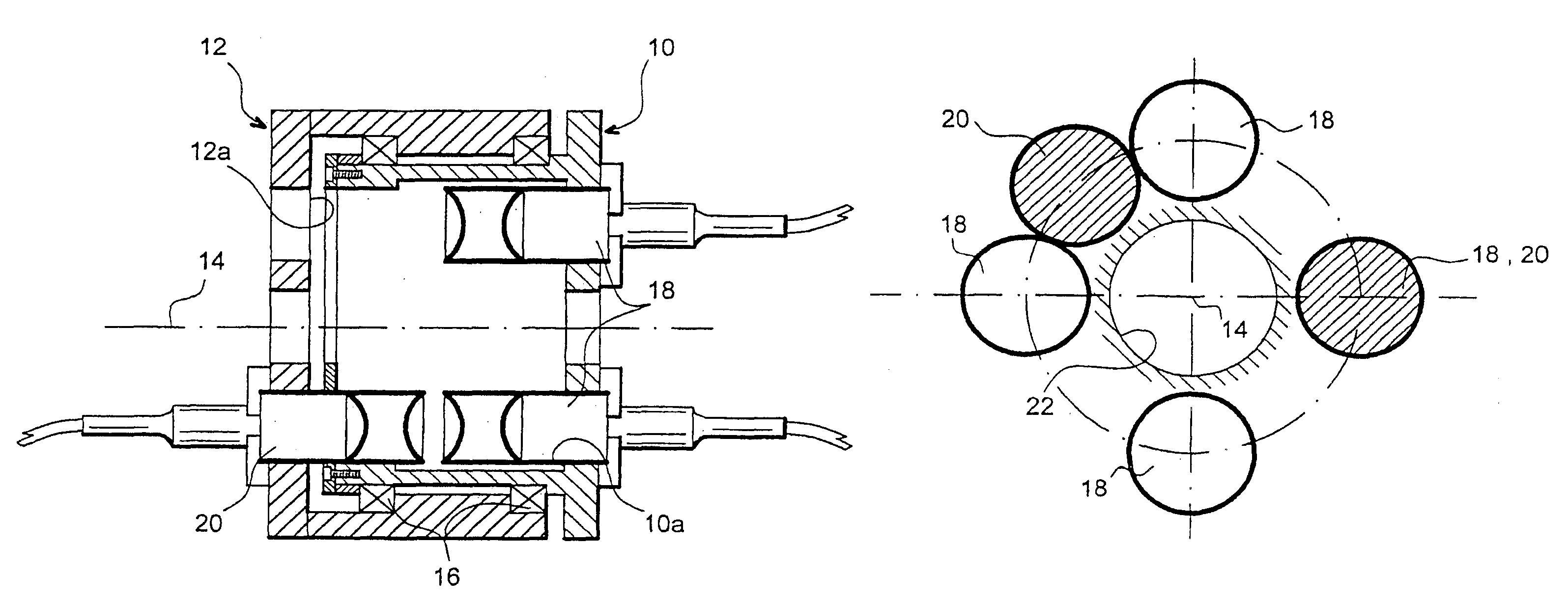
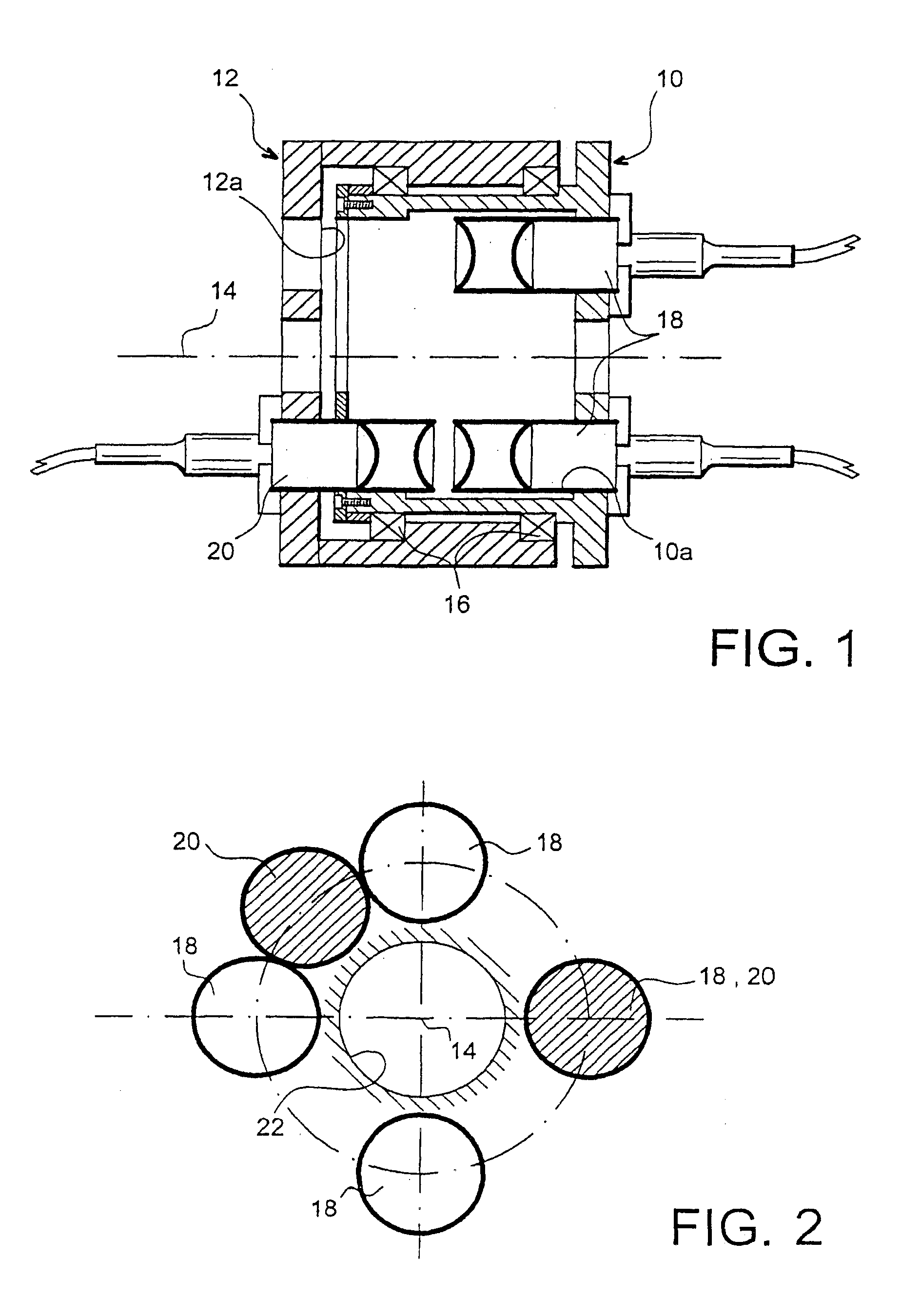
[0041]In FIG. 1 we have represented the main part of a rotating optical joint of the “off-axis” type in the invention. As this diagram illustrates, the joint comprises a first organ 10 and a second organ 12, with a common axis 14. Organs 10 and 12 are able to rotate independently of one another on this common axis 14. To this end, bearings 16 can notably be interposed between these organs 10 and 12.

[0042]As is illustrated equally by FIG. 1, the first organ 10 comprises an end face 10a located opposite an end face 12a of the second organ 12. These end faces 10a and 12a are perpendicular to axis 14 which is common to both organs.

[0043]In the preferred embodiment of the invention illustrated as an example in FIGS. 1 and 2, the first organ 10 supports four first collimators 18, and the second organ 12 supports two second collimators 20. More specifically, the first collimators 18 extend outwards from the end face 10a of the first organ 10 and the second collimators 20 extend outwards fr...


PUM


Abstract

A rotating optical joint has two organs which are able to rotate independently of one other on a common axis (14). Collimators (18, 20) are mounted directly opposite one another on the organs, in an arrangement such that they permanently provide a variation of the power of the transmitted signal of less than 25%, during relative rotation of the said organs. The total number of collimators (18, 20) is preferably less than or equal to eight. Advantageously, three collimators (20) are mounted on one of the organs and four collimators (18) are mounted on the other organ.

Description

TECHNICAL FIELD[0001]The invention concerns a rotating optical joint intended to transmit data in an optical form between two organs able to rotate independently of one another on a common axis.[0002]More precisely, the invention concerns a rotating optical joint designed to provide transmission of data in a manner which is offset from the common axis of the said organs.[0003]Such joints can be used in many different technical fields, such as radar or tank turrets, helicopter rotors, etc.CURRENT STATE OF TECHNOLOGY[0004]To transmit data between two organs which must rotate independently of one another, one traditional solution consists in using rotating electrical joints.[0005]In joints of this type, electrical signals are transmitted by mechanical parts which rub against one another.[0006]Rotating electrical joints do however have major disadvantages. Among these disadvantages one must mention notably the wear and tear of the parts due to the mechanical contact, which requires regu...

Claims


Application Information

Patent Timeline
Patent Type & Authority Patents(United States)
IPC IPC(8): G02B6/36G02B6/32
CPCG02B6/3604G02B6/32
Inventor MERCEY, THIBAUTSABATIER, JACQUES
Owner AIR PRECISION
Why Eureka
Try Eureka