
Motorcycle lateral suspension mechanism

Inactive Publication Date: 2005-05-31
ANIBAS KEVIN J
View PDF18 Cites 25 Cited by
  • Summary
  • Abstract
  • Description
  • Claims
  • Application Information

AI Technical Summary

Benefits of technology

[0013]In the broadest concept, the mechanism includes a swingarm pivot axle rotatably securing the swingarm member to the frame. A pair of flexure members, each are secured to the frame by a plurality of flexure member mounts, and each include an aperture accepting the swingarm pivot axle. Also present is a means for adjustably controlling the degree of lateral axial deflection of the swingarm pivot axle and associated swingarm member relative to the frame and attached flexure members during operation of the motorcycle.
[0014]In one embodiment, the adjustable controlling means includes a cam assembly encircling the swingarm pivot axle. The cam assembly comprising a cam stationary member rigidly secured to the frame and a cam rotating member rotatable by an actuator, the cam members including at least one ramped contact surface there between. An actuator rotates the cam rotatin

Problems solved by technology

While the older “flexible” chassis absorbed some of the energy of a bump, the newer “rigid” chassis cannot.
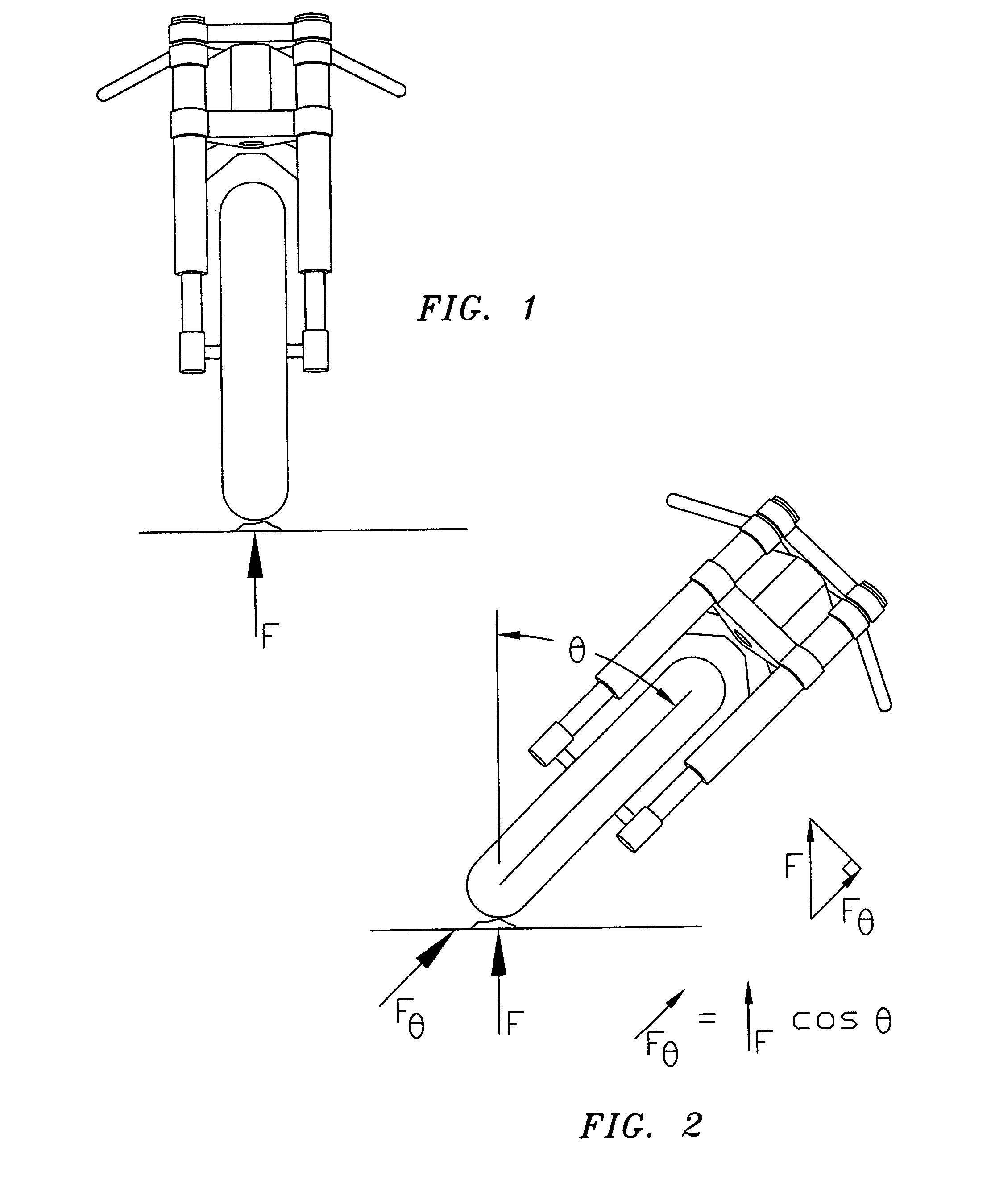
The modern chassis are rigid to the point that when leaned-over, irregularities in the road surface sometimes deflect the tires in an arc about the center of mass of the machine, resulting in a loss of traction.
One might expect the suspension to absorb this bump energy, but this is not always possible.
Some increase in friction in the telescopic front fork may also be present when cornering, as it is loaded at an angle to its normal plane of operation.
Because of this, in some cases, when an irregularity in the road surface is encountered, the tires may leave the road surface or be unloaded to the point that they lose traction.
This can result in chatter, instability, or even momentary “high-side” crash inducing losses of traction.
Since the suspension must accommodate braking dive forces, stability, comfort, and cornering clearance constraints, softer springs and modified damping are not a viable option to deal with this lessened force.
A fully active suspension system may be an answer to this problem, but complexity and power requirements make it impractical at present.
It is apparent that some chassis flex or lateral suspension movement can be beneficial to handling in some situations, and detrimental in others.

Method used


Image

  • Motorcycle lateral suspension mechanism
  • Motorcycle lateral suspension mechanism
  • Motorcycle lateral suspension mechanism

Examples


first embodiment

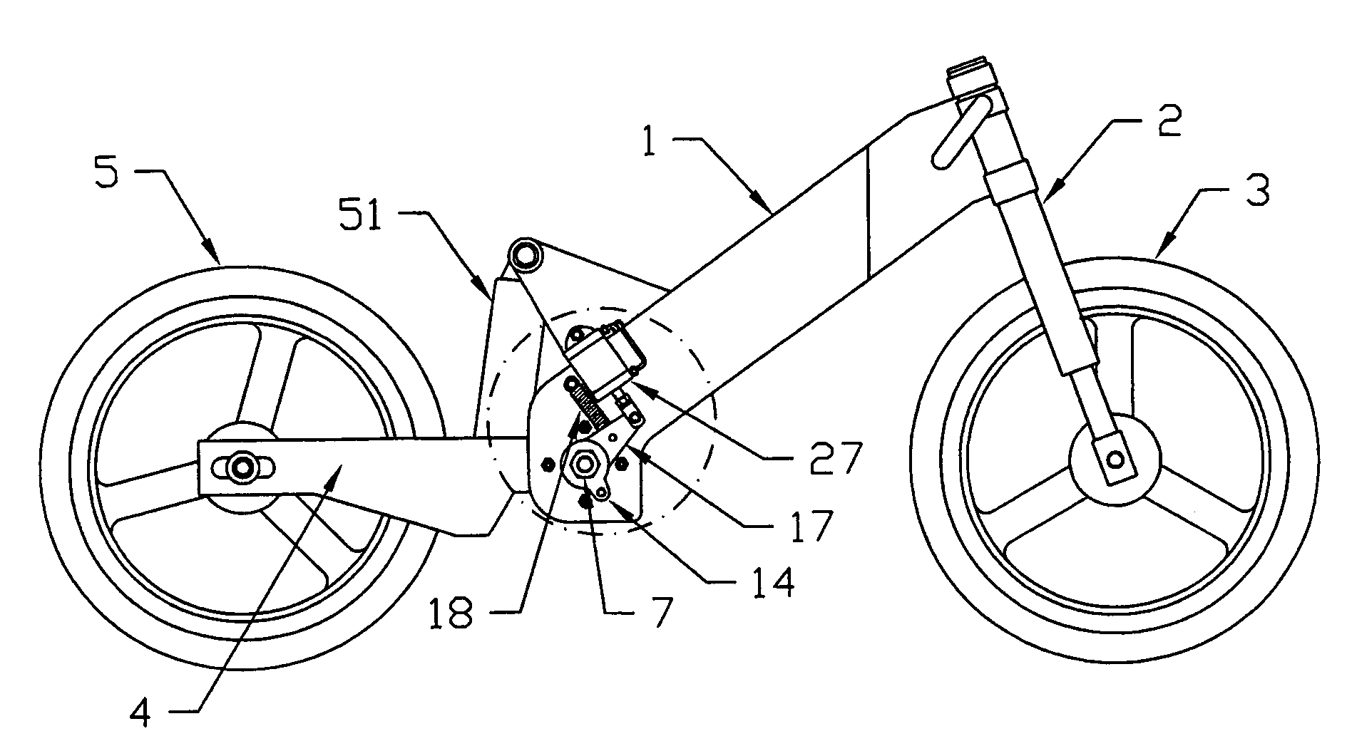
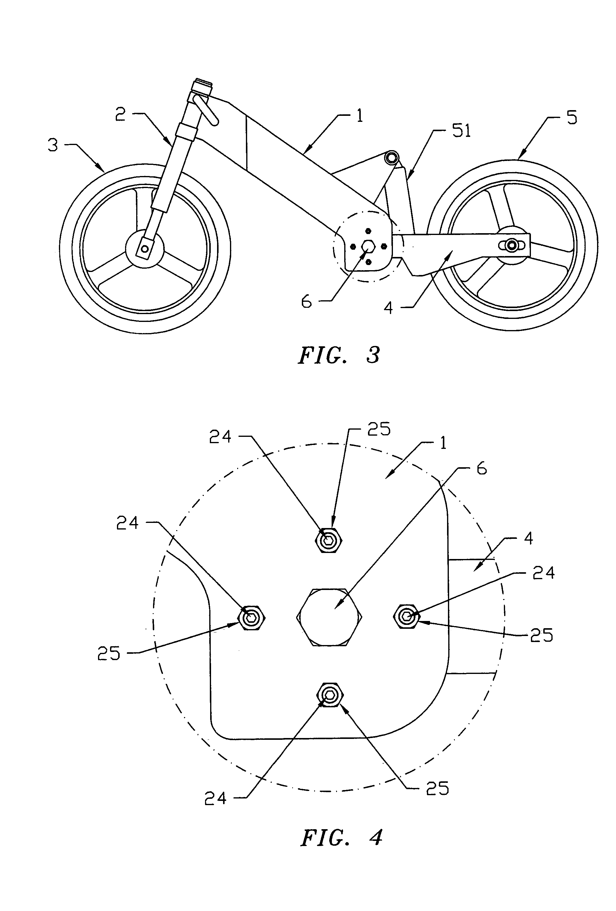
[0095]The invention is a mechanism that is added to or built into the swingarm pivot of a motorcycle chassis. In the invention, shown in FIGS. 3 through 13, a swingarm pivot axle 6 is fitted into bushings 8 which are pressed into apertures in the motorcycle frame 1. A concentric shoulder 31 on one end of the swingarm pivot axle 6 provides a close slideable fit into one of the bushings 8. If the motorcycle frame 1 is of suitable construction and material, the swingarm pivot axle 6, optionally, is fitted into apertures in the motorcycle frame 1 without bushings 8. The shoulder 31 end of the swingarm pivot axle 6 includes a hex head, or other feature, to retain the axle 6 to the frame 1, while a self-locking nut 7 is tightened on the opposite end of the axle 6, which is threaded. When installed into the bushings 8, the hex head of the axle 6 is on one outboard side of the frame 1 and the threaded end and self-locking nut 7 is on the other outboard side of the frame 1. On the inboard si...

second embodiment

[0099]In the invention, shown in FIGS. 14 through 17, an engine case or central frame member 12 is used for additional support to the swingarm member 4 pivot. The swingarm member 4 bearing area is separated so that it straddles the engine case or central frame member 12. Each side of the swingarm member 4 includes a needle bearing 9, a collar 10, two trust bearings 11, and two end caps and seals 13. The swingarm pivot axle 6 passes through bushings 8 in the frame 1 and through a bushing 32 in the engine case or central frame member 12. A plurality of threaded flexure member mounts 24 are threaded into an array of threaded apertures in both sides of the engine case or central frame member 12, as shown in FIG. 16. Flexure members 23 are fastened to the threaded flexure member mounts 24 by locknuts 26 to each side of the case or frame member 12. The threaded flexure member mounts 24 have internal hex features, or other such features, allowing the mounts 24 to be turned to adjust the pl...


PUM


Abstract

A device for providing adjustable, deployable, controlled flex and lateral suspension movement to a motorcycle chassis. This is accomplished by a swingarm pivot mechanism, that when operated, variably allows the swingarm member to move laterally, controlled by flexure members, and constrained within selected limits. The mechanism is controlled by a logic unit acting on inputs such as lean angle, road speed, transmission gear position, engine speed, throttle position, brake application, suspension position, and a rider override switch. In another embodiment, the mechanism is used without an actuator, and is manually adjusted for flex and performance per conditions and rider preference.

Description

CROSS-REFERENCE TO RELATED APPLICATIONS, IF ANY[0001]Not applicable.STATEMENT REGARDING FEDERALLY SPONSORED RESEARCH OR DEVELOPMENT[0002]Not applicable.REFERENCE TO A MICROFICHE APPENDIX, IF ANY[0003]Not applicable.BACKGROUND OF THE INVENTION[0004]1. Field of the Invention[0005]The present invention is a device for providing deployable, adjustable, controlled flex and lateral suspension movement to a motorcycle chassis.[0006]2. Background Information[0007]This invention is a device for providing deployable, adjustable, controlled flex and lateral suspension movement to a motorcycle chassis for the purpose of enhancing handling characteristics when leaned-over, and at slower speeds, but without compromising stability when the motorcycle is upright, and at high speeds.[0008]Over the last twenty years or so, advances in motorcycle chassis and tire design have delivered great improvements in handling characteristics, especially with respect to high-speed stability. Unlike earlier chassi...

Claims


Application Information

Patent Timeline
IPC IPC(8): B62K25/04
CPCB62K25/04B62K2025/044
Inventor ANIBAS, KEVIN J.
Owner ANIBAS KEVIN J
Learn More