Vehicle fuel pulse damper

Inactive Publication Date: 2005-06-07
EATON INTELLIGENT POWER LIMITED
View PDF31 Cites 53 Cited by
  • Summary
  • Abstract
  • Description
  • Claims
  • Application Information

AI Technical Summary

Benefits of technology

[0005]In one embodiment of the invention, the metallic damper body includes first and second metallic housings that mate together to define the chamber and to trap a peripheral edge of the flexible gas impermeable diaphragm such that the diaphragm divides the chamber into a first chamber that communicates to pressurized fuel entering the first fitting and leaving the quick connect fitting and a second gas-filled or air-filled chamber that allows the diaphragm to flex in a manner to attenuate or dampen fuel pressure pulses in the fuel system. The quick connect fitting can be formed integrally with the damper body or preformed as a separate component and fastened thereto metallurgically by brazing or welding. The first fitting also can be formed integrally with the damper body or preformed as a separate metal component and fastened thereto metallurgically by brazing or welding.

Problems solved by technology

The fuel injector pulses have been found to generate problems with precise fuel delivery to the engine as engine fuel control systems have become more precise to meet federal emission regulations.
This problem has necessitated the existing fuel pulse damper to be packaged nearer to the source of the noise (pressure pulses); i.e., nearer to the fuel rail on the engine.

Method used


Image

  • Vehicle fuel pulse damper
  • Vehicle fuel pulse damper
  • Vehicle fuel pulse damper

Examples


Embodiment Construction

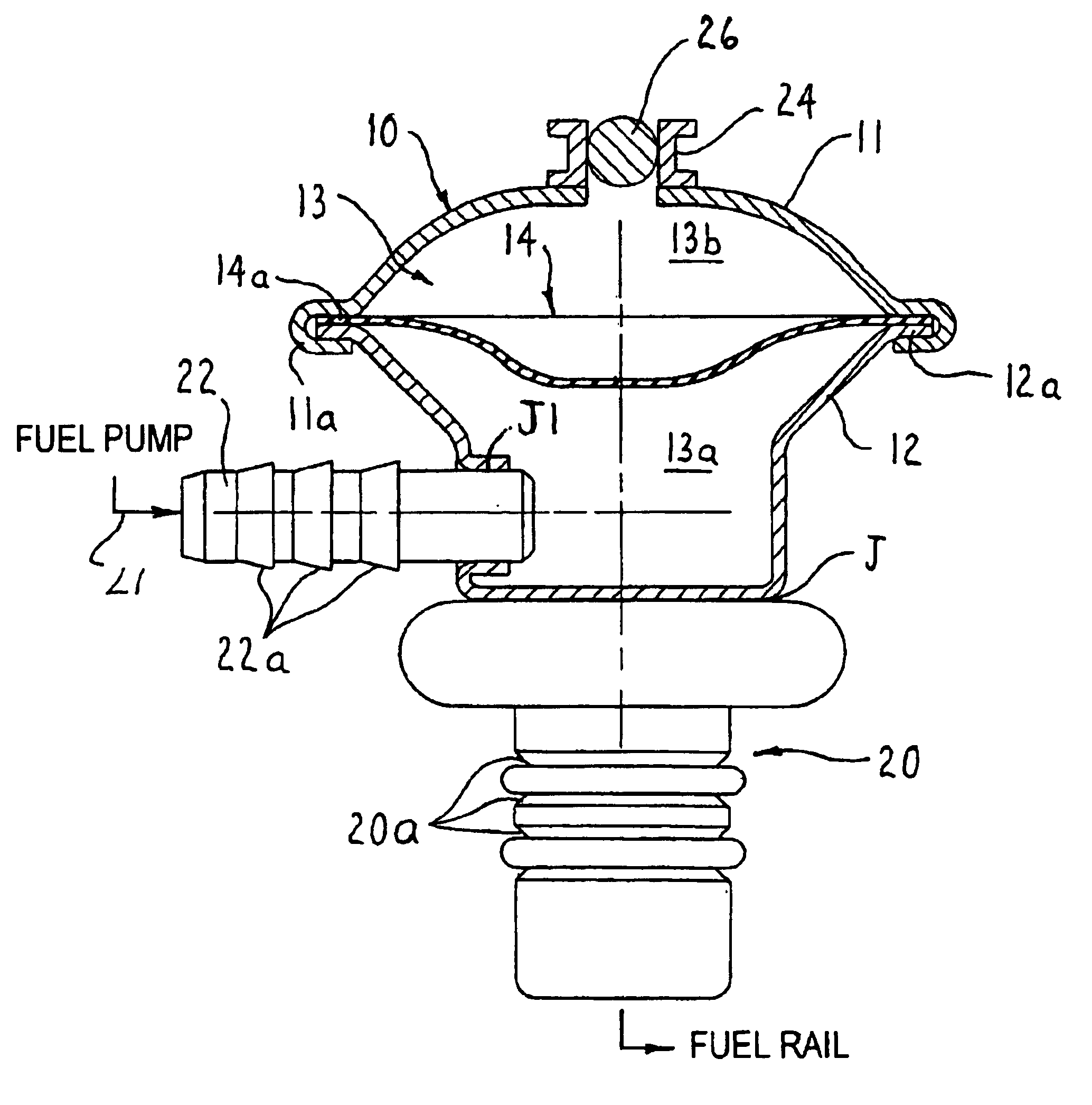
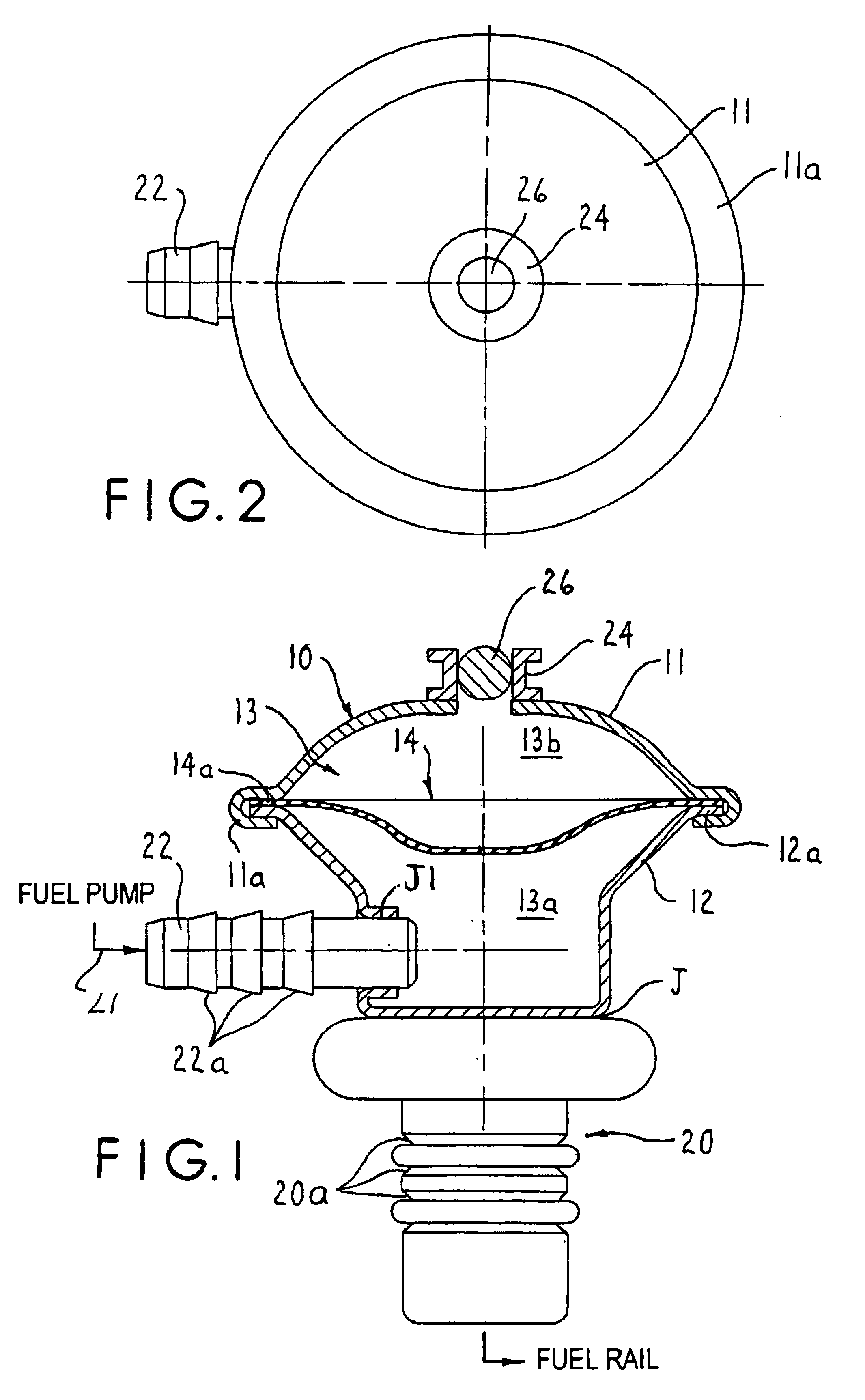
[0014]Referring to FIGS. 1-2, an embodiment of the invention is illustrated for purposes of illustration and not limitation. The fuel pressure pulse damper is shown comprising a damper body 10 that comprises first and second metallic housings 11, 12 that mate together to define a chamber 13 therein and to trap a peripheral edge 14a of a flexible gas-impermeable diaphragm 14 such that the diaphragm divides the chamber 13 into a first chamber 13a that communicates to pressurized fuel entering the first (barbed) fitting 22 and leaving the quick disconnect fitting 20 and a second gas-filled or air-filled chamber 13b that allows the diaphragm 14 to flex in a manner to attentuate (reduce) fuel pressure pulses exceeding a preselected value in the fuel system to dampen the fuel pressure pulses and smooth operation of the fuel delivery system. The chamber 13b can be filled with pressurized gas or ambient air. For example, the housings 11, 12 and diaphragm 14 can be assembled in pressurized s...


PUM


Abstract

A fuel pressure pulse damper includes metallic damper body defining a chamber in which a flexible diaphragm is received in a manner to dampen fuel pressure pulses between a fuel pump and fuel injectors of a vehicle fuel system. The damper body includes a barbed fitting to receive fuel form the fuel pump and quick connect fitting for connection to a fuel rail for supplying pressurized fuel to fuel injectors of the vehicle engine.

Description

FIELD OF THE INVENTION[0001]The present invention relates to a fuel pressure pulse damper for a vehicle fuel system.BACKGROUND OF THE INVENTION[0002]Hydraulic pulse dampers are used on vehicles to eliminate or reduce hydraulic pulses caused by the fuel injector and the fuel pump. Typically, the damper is mounted in-line near the vehicle engine or in the fuel sender unit in the vehicle fuel tank. The fuel injector pulses have been found to generate problems with precise fuel delivery to the engine as engine fuel control systems have become more precise to meet federal emission regulations. This problem has necessitated the existing fuel pulse damper to be packaged nearer to the source of the noise (pressure pulses); i.e., nearer to the fuel rail on the engine. A widely used in-line pulse damper includes two barb-type fittings which allow it to be spliced into the fuel line.[0003]An object of the present invention is to provide an improved fuel pressure pulse damper including a quick ...

Claims


Application Information

Patent Timeline
Patent Type & Authority Patents(United States)
IPC IPC(8): F16L55/04F16L55/053
CPCF16L55/053Y10T137/7836
Inventor KIPPE, BRADLEY N.THATER, BARRY L.
Owner EATON INTELLIGENT POWER LIMITED
Why Eureka
Try Eureka