Quantized feed system for solid freeform fabrication

a feed system and solid freeform technology, applied in additive manufacturing processes, manufacturing tools, coatings, etc., can solve the problems of shortening the time to develop prototype parts, sacrificing the ability to selectively disperse multiple colors, and quickly producing limited numbers of parts in rapid manufacturing processes. , to achieve the effect of substantially reducing the amount of radiant heat generated by an sdm apparatus

Inactive Publication Date: 2005-06-07
3D SYST INC
View PDF9 Cites 50 Cited by
  • Summary
  • Abstract
  • Description
  • Claims
  • Application Information

AI Technical Summary

Benefits of technology

[0020]It is an advantage of the present invention that it is no longer necessary to maintain a large quantity of build material in a flowable state in a remote reservoir at an elevated temperature in an SDM apparatus.
[0021]It is another advantage of the present invention that materials can be used by an SDM apparatus without requiring the implementation of special handling procedures for the material.
[0022]It is yet another advantage of the present invention that the amount of radiant heat generated by an SDM apparatus is substantially reduced.
[0023]It is still yet another advantage of the present invention feed system that ink jet print heads can be utilized to build three-dimensional objects by SFF techniques having visual attributes such as color.
[0024]These and other aspects, features, and advantages are achieved according to the method and apparatus of the present invention that employs a unique build material feed system that delivers a discrete amount of build material on an as needed basis in a non-flowable state to a dispensing device. After the material is delivered to the dispensing device, it is changed from the non-flowable state to a flowable state wherein it may then be selectively dispensed to form a three-dimensional object in a layerwise fashion.

Problems solved by technology

For instance, SFF technologies dramatically shorten the time to develop prototype parts and can quickly produce limited numbers of parts in rapid manufacturing processes.
This is generally because there are substantial differences between the two processes requiring different solutions to different problems.
However, this sacrifices the ability to selectively dispense multiple colors from the print head when forming the object.
The differences mentioned above are significant and create a number of problems to be resolved.
For instance, the amount of material deposited in SDM techniques, both in volume and in mass, can be so substantial that it is generally considered impractical to mount a reservoir directly on die ink jet print head to hold all of the material.
Undesirably, start up times are longer for SDM techniques using ink jet print heads than in two-dimensional printing with ink jet print heads due to the length of time necessary to initially heat the solidified material in the large remote reservoir to its flowable state.
In addition, a significant amount of energy is required to maintain the large quantity of material in the flowable state in the reservoir and in the delivery system during the build process.
This undesirably generates a significant amount of heat in the build environment.
This would multiply the complexity and cost of such a system and is generally not practical.
However, these prior expedients are directed to feed systems for two-dimensional printing and do not address the problems confronted in SDM techniques, such as how to handle and deliver the significantly larger quantity of build material needed to form three-dimensional objects.
Another problem that is unique to SDM techniques is that the layers being formed must be shaped or smoothed during the build process to establish a uniform layer.
However, the planarizer produces waste material during the build process that must be handled.
Normally this is not a concern when working with non-reactive materials; however, it can become a problem when reactive materials are used.
For example, most photopolymers are reactive, and excessive contact to human skin may result in sensitivity reactions.
However, SDM operators who normally handle non-reactive materials consider additional handling procedures inconvenient and, if possible, would prefer they be eliminated.

Method used


Image

  • Quantized feed system for solid freeform fabrication
  • Quantized feed system for solid freeform fabrication
  • Quantized feed system for solid freeform fabrication

Examples


Embodiment Construction

[0035]The present invention provides its benefits across a broad spectrum of SFF processes. While the description which follows hereinafter is meant to be representative of a number of such applications, it is not exhaustive. As will be understood, the basic apparatus and methods taught herein can be readily adapted to many uses. It is intended that this specification and the claims appended hereto be accorded a breadth in keeping with the scope and spirit of the invention being disclosed despite what might appear to be limiting language imposed by the requirements of referring to the specific examples disclosed.

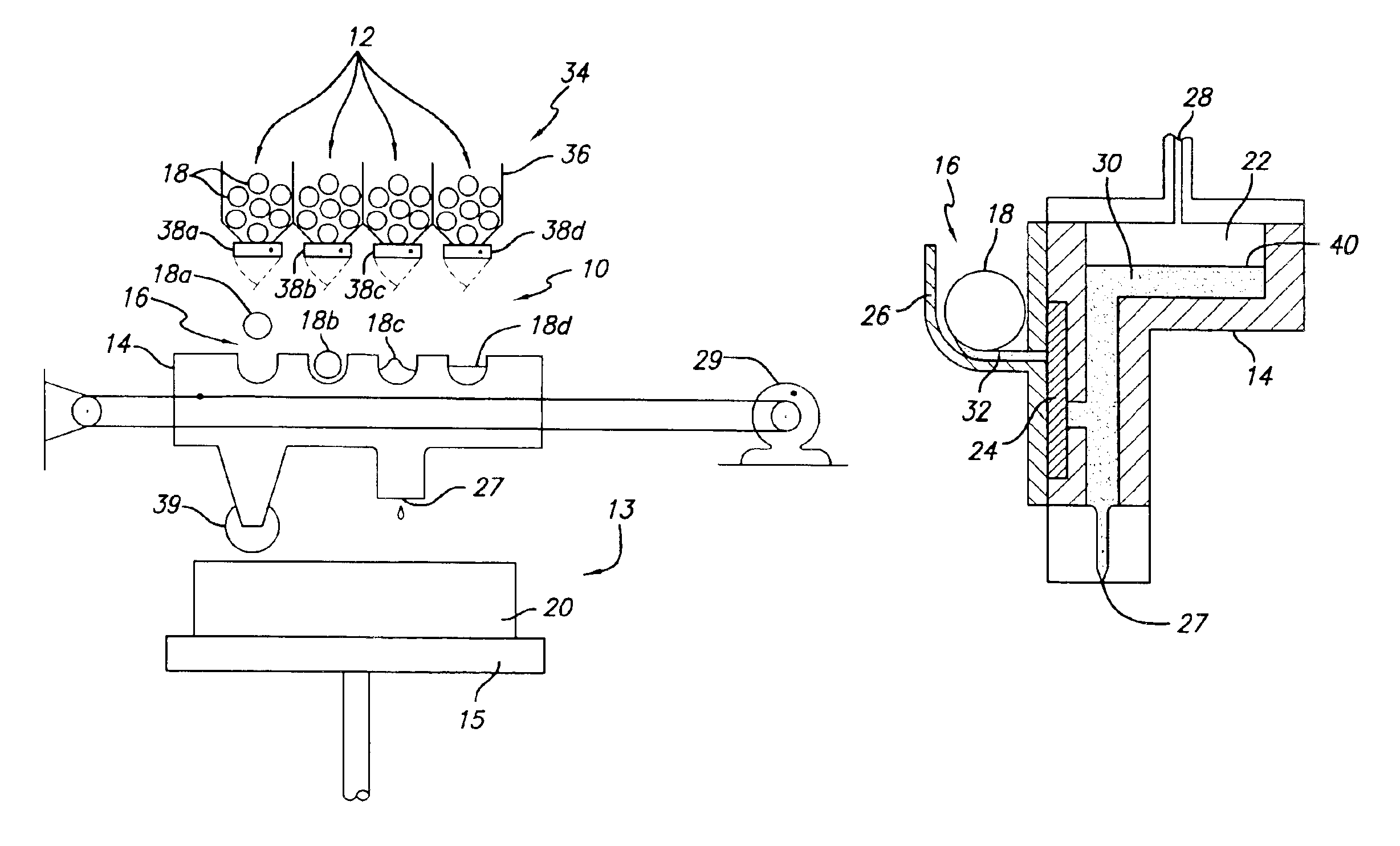
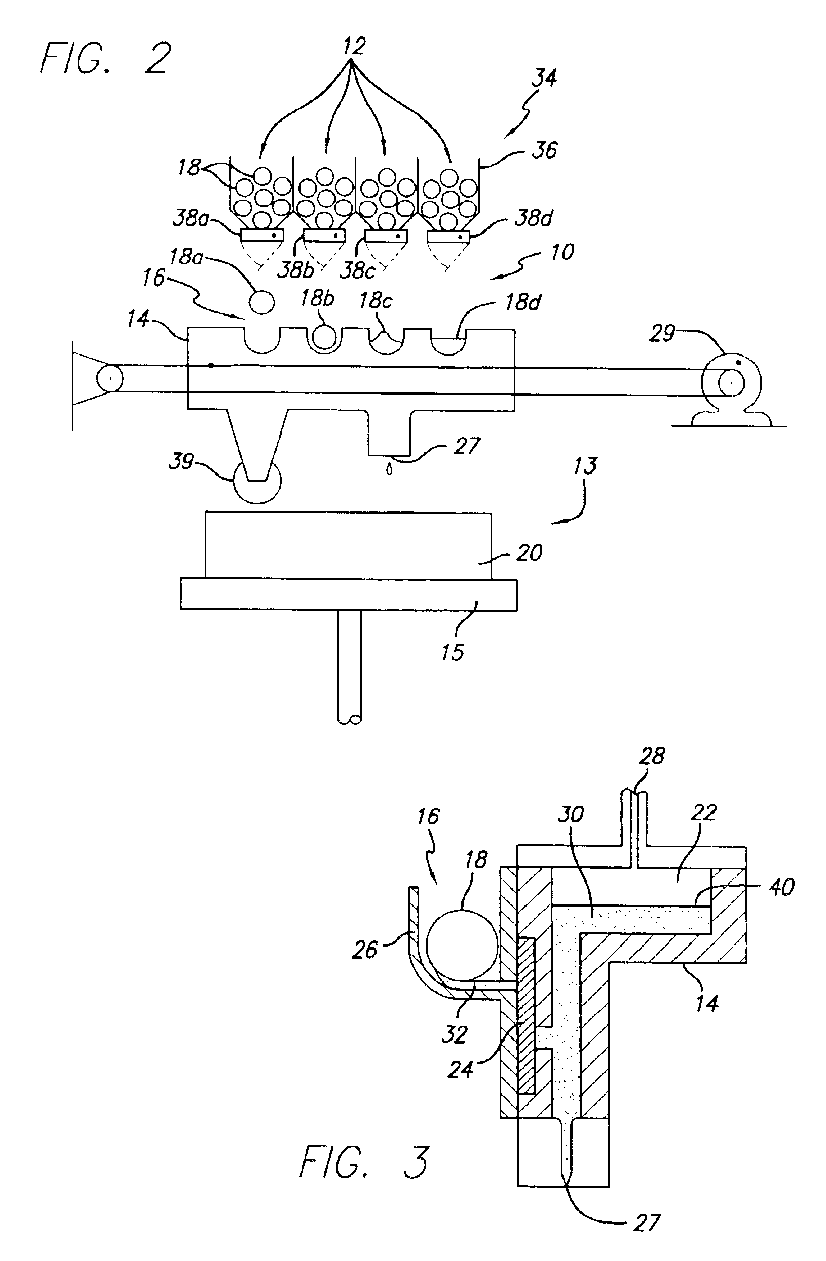
[0036]While the present invention is applicable to all SFF techniques and objects made therefrom, the invention will be described with respect to solid deposition modeling utilizing a build material that is dispensed in a flowable state. However it is to be appreciated that the present invention can be implemented with any SFF technique utilizing a wide variety of build mate...


PUM

PropertyMeasurementUnit
spherical diameteraaaaaaaaaa
physical characteristicaaaaaaaaaa
colorsaaaaaaaaaa

Abstract

A material feed system for solid freeform fabrication. The build material is delivered in discrete or quantized amounts by the feed system in a non-flowable state to the dispensing device and the material is then changed to a flowable state prior to being dispensed. The feed system can be used to build three-dimensional objects in color, if desired. In one embodiment individual cartridges with build material are loaded into a magazine on the feed system which is integrated with a waste removal system. As the build material is expelled from the cartridges, waste material is deposited into the cartridge. Once all the build material has been expelled, the waste material is hermetically sealed in the spent cartridge which is then ejected from the system. The hermetically sealed cartridges protect operators from contact with the reactive waste material making the system safe for the office environment.

Description

BACKGROUND OF THE INVENTION[0001]1. Field of the Invention[0002]The invention relates in general to a material feed system for solid freeform fabrication and, in particular, to a quantized feed system that can selectively feed discrete portions of material directly to a solid freeform fabrication device to build three-dimensional objects. Because the feed system is quantized, the system can be used to build three-dimensional objects in color or to dispense more than one material. In addition, the feed system can be integrated with a hermetically sealed waste removal system wherein reactive materials can be handled without special handling procedures.[0003]2. Description of the Prior Art[0004]Recently, several new technologies have been developed for the rapid creation of models, prototypes, and parts for limited run manufacturing. These new technologies can generally be described as solid freeform fabrication, herein referred to as “SFF”. Some SFF techniques include stereolithograph...

Claims


Application Information

Patent Timeline
Patent Type & Authority Patents(United States)
IPC IPC(8): B29C67/00B05D3/00
CPCB29C67/0092B29C64/40B33Y40/00B33Y10/00B33Y30/00B29C64/106B33Y40/20
Inventor VARNON, DAVID MONTGOMERYFONG, JON JODYBISHOP, RAYMOND J.
Owner 3D SYST INC
Why Eureka
Try Eureka