Articles with flashing lights

a technology of flashing lights and flashing parts, which is applied in the field of lighting devices and systems, can solve the problems of confined, and shortening the service life of lighting systems,

Inactive Publication Date: 2005-06-14
CHEERINE DEVMENT HONG KONG
View PDF122 Cites 31 Cited by
  • Summary
  • Abstract
  • Description
  • Claims
  • Application Information

AI Technical Summary

Problems solved by technology

These lighting systems, however, suffer from a number of deficiencies.
There is typically no on-off switch for the lighting system, and thus the system is “on” all the time, draining the power source, which is typically a small battery.
Even if the only portion of the system that is operating is an oscillator or timer, the power drain over time is cumulative, thus leading to shorter-than-desirable battery life.
Another deficiency is the limited utility of the system, confined as it is to footwear.
Prior art systems, such as those disclosed in U.S. Pat. No. 5,894,201, however, do not include these applications.
Because the lighting system is incorporated into footwear, there may be no other switch, and thus the opportunities for turning the system on or off are limited to actuating the inertial switch, i.e. to running.

Method used


Image

  • Articles with flashing lights
  • Articles with flashing lights
  • Articles with flashing lights

Examples


Embodiment Construction

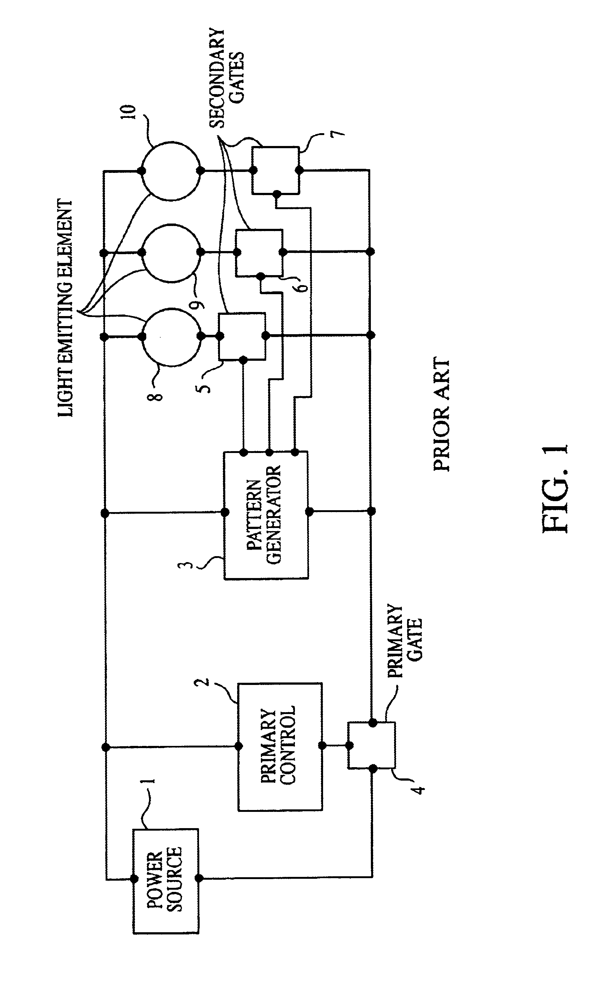
[0021]Lighting or illumination systems for decoration or safety on clothing and personal articles must necessarily be compact and light-weight, so that the article to be illuminated can be easily adapted to receive and hold the illumination system. FIG. 1 represents a block diagram of such a system. The Illumination system depicted in FIG. 1 comprises a power source 1, a primary control means 2, a pattern generation means 3 and a primary gate 4. There is a plurality of lamps 8, 9 and 10, secondary gates 5, 6, and 7, and a pattern-generation means 3 for generating a pattern of signals to control the secondary gates 5, 6 and 7. The primary control means 2 controls the opening and closing of the primary gate 4. When the primary gate 4 is closed, it enables the flow of current through the circuit, allowing the circuit to operate. The pattern-generation means 3 generates a pattern of signals and each generated signal separately controls the opening and closing of a respective secondary g...


PUM


Abstract

Illuminating devices may be added to clothing and accessories worn by persons. Articles to which the illuminating devices may be added include footwear, hair-control articles, belts, suspenders, backpacks, purses, book-bags, vests and the like. The illuminating devices are necessarily compact in nature, consisting primarily of flashing lights and a power-and-control circuit that controls and enables the flashing of the lights. The lights may be flashed sequentially, in-phase, randomly, or in other desirable patterns, and the lights may also fade-on or fade-off. Controls may include an inertial switch, a push-button or touch-switch, and an on-off toggle switch.

Description

FIELD OF THE INVENTION[0001]This invention relates to clothing and accessories, and more particularly to an improved system for illuminating devices incorporated into clothing and accessories.BACKGROUND OF THE INVENTION[0002]Lighting systems have been incorporated into footwear, generating distinctive flashing of lights for a person wearing the footwear. These systems generally have an inertial switch, so that when a runner's heel strikes the pavement, the switch moves in one direction or another, triggering a response by at least one circuit that typically includes a power source and a means for powering and controlling the lights. The resulting light flashes are useful in identifying the runner, or at least the presence of a runner, because of the easy-to-see nature of the flashing lights. Thus, the systems may contribute to the fun of exercising while adding a safety feature as well.[0003]These lighting systems, however, suffer from a number of deficiencies. There is typically no...

Claims


Application Information

Patent Timeline
Patent Type & Authority Patents(United States)
IPC IPC(8): A41D27/00A41D27/08
CPCA41D27/085
Inventor WONG, WAI KAI
Owner CHEERINE DEVMENT HONG KONG
Why Eureka
Try Eureka