Shaft locking device for bearing assemblies

a technology of locking device and bearing assembly, which is applied in the direction of couplings, mechanical devices, rigid supports of bearing units, etc., can solve the problems of mislaid, inability to easily separate the collapsing from the bearing assembly, etc., and achieve the effect of convenient subsequent reliable installation and efficient pre-assembling

Inactive Publication Date: 2005-06-21
REGAL BELOIT AMERICA
View PDF20 Cites 17 Cited by
  • Summary
  • Abstract
  • Description
  • Claims
  • Application Information

AI Technical Summary

Benefits of technology

[0005]In overcoming these problems with the prior art there is provided a bearing assembly wherein the locking collar may be efficiently pre-assembled on the inner bearing ring at the factory and remain properly positioned on the inner bearing ring during installation onto a shaft. In this way, the collar may not be readily separated from the bearing assembly and mislaid. Moreover, this preassembly ensures that the collar is in proper position on the inner bearing ring which facilitates subsequent reliable installation of the collar and inner bearing ring on the shaft.
[0006]In accomplishing these objectives, the inner diameter of the compressible annular locking collar is provided with a protrusion which extends radially inwardly. When the locking collar is disposed about the finger extensions of the inner ring, the protrusion is disposed within a recessed groove which extends at least partially along the collective outer annular surface defined by the finger extensions for precisely locating and orienting the collar. According to a feature of the invention, when the inner ring finger extensions and the locking collar are in their free states, the inner diameter of the protrusion is slightly smaller than the outer diameter of the finger extension groove. In this way, the collar may be snapped over the finger extensions and into proper position on the inner ring prior to installation on a shaft, i.e., in the factory. The locking collar then remains in proper position on the finger extensions as the bearing assembly subsequently is installed onto the shaft. In one embodiment, a one-piece locking collar body has an integrally formed protrusion adapted for snap action engagement with a finger extension recess, in another embodiment the locking collar has separate resilient O-ring engageable with the finger extension recess, and in another embodiment, the locking collar and finger extensions are formed with screws which permit threaded advancement of the locking collar into preassembled position. In each case, following preassembly of the bearing assembly an a shaft, a locking screw may thereafter be tightened to deform the finger extensions into secure engagement with the shaft.

Problems solved by technology

In this way, the collar may not be readily separated from the bearing assembly and mislaid.

Method used


Image

  • Shaft locking device for bearing assemblies
  • Shaft locking device for bearing assemblies
  • Shaft locking device for bearing assemblies

Examples


Embodiment Construction

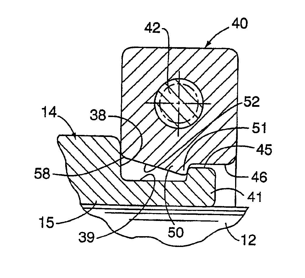
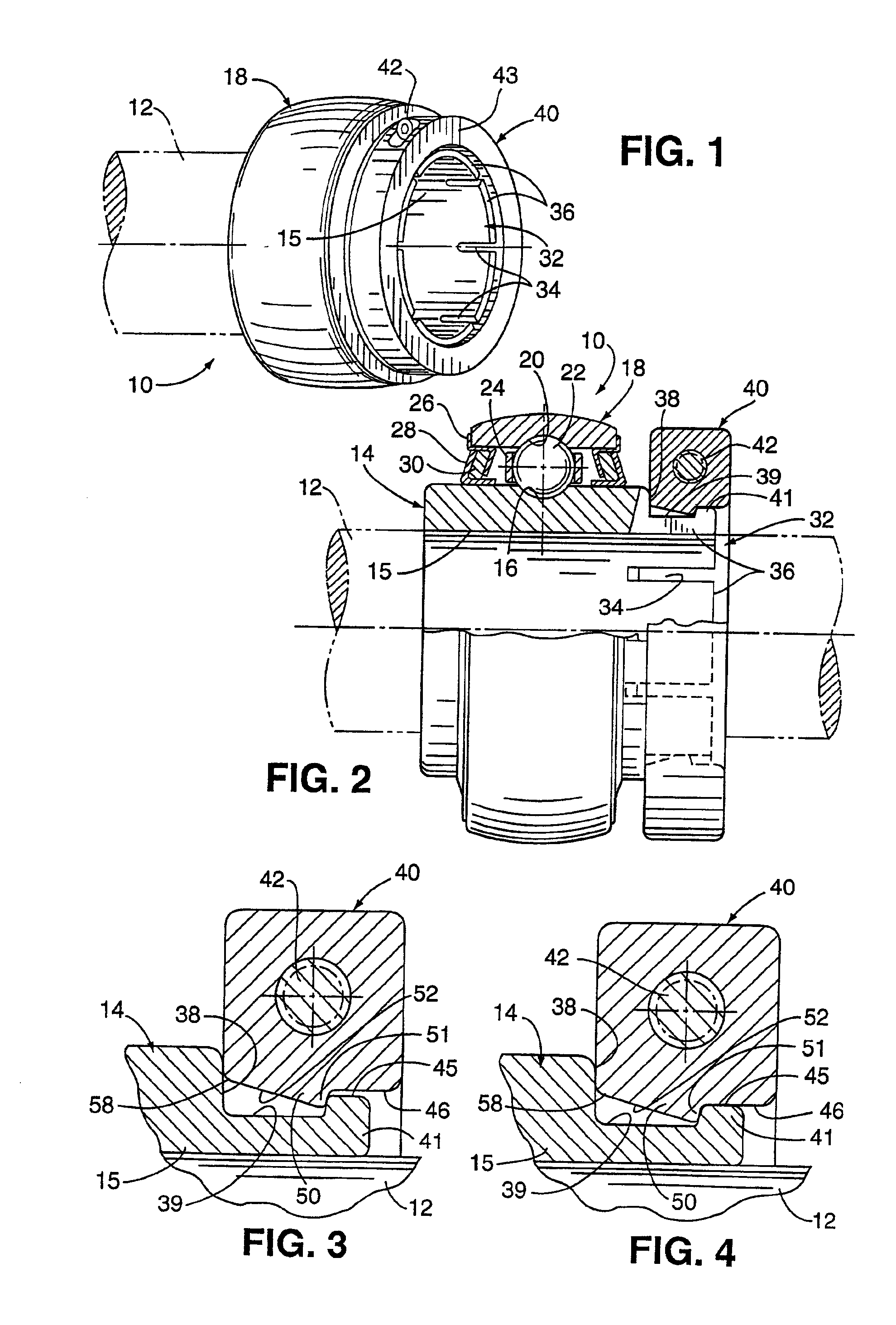
[0020]Referring now more particularly to FIGS. 1 and 2 of the drawings, there is shown an illustrative bearing assembly 10 embodying the present invention mounted on a shaft 12 (shown in phantom). The bearing assembly 10 includes an annular inner ring 14 having a grooved raceway 16 formed in a main body portion 15 thereof. Surrounding the inner ring 14 in spaced relation thereto is an annular outer ring 18 having a grooved raceway 20 disposed in opposed relationship to the inner raceway 16, the raceways 16, 20 serving to receive in nesting relationship a plurality of spaced balls or rolling elements 22. The rolling elements 22 in this case are disposed in rolling element pockets of a conventional cage 24. Preferably, the inner and outer raceways are wear hardened for extending the life of the bearing.

[0021]While not illustrated in the drawings, the assembly 10 includes a convention means for lubricating movement of the rolling elements 22. To maintain lubrication to the rolling elem...


PUM


Abstract

A bearing assembly wherein the inner diameter of the slotted compressible annular locking collar is provided with a protrusion which extends radially inwardly, and finger extensions of the inner ring are provided with a recessed groove which extends at least partially along the collective outer annular surface of the finger extensions. When the locking collar is disposed about the finger extensions of the inner ring, the protrusion is disposed within the recessed groove to retain the locking collar on the inner ring. The inner ring finger extensions and the locking collar are relatively sized such that when they are in their free states, the inner diameter of the protrusion is slightly smaller than the outer diameter of the recessed groove, such that the collar may be snapped over the finger extensions and into proper position on the inner ring prior to installation on a shaft. The protrusion may be an integrally formed part of the locking collar or a separate resilient member. In one embodiment, the locking collar and finger extensions are formed with cooperating threads.

Description

[0001]This is a divisional application of U.S. patent application Ser. No. 09 / 235,691, filed Jan. 22, 1999, now U.S. Pat. No. 6,200,039, which is a divisional application of U.S. application Ser. No. 08 / 798,284, filed on Feb. 7, 1997, now U.S. Pat. No. 5,863,137.FIELD OF THE INVENTION[0002]The present invention relates to bearing assemblies, and more particularly, to a bearing assembly having improved means for securing the inner bearing ring of the assembly onto a shaft.BACKGROUND OF THE INVENTION[0003]Various arrangements are known in the art for securing the inner bearing ring of a bearing assembly onto a rotating shaft. Such arrangements have included shaft engaging set screws and shaft-surrounding locking collars. Such locking collars include locking or tightening means, generally in the form of one or more locking screws. In the so-called SKWEZLOC® arrangement disclosed in U.S. Pat. Nos. 4,537,519 and 4,728,203, the inner ring has finger extensions which, when compressed with ...

Claims


Application Information

Patent Timeline
Patent Type & Authority Patents(United States)
IPC IPC(8): F16C35/04F16C35/063F16C35/07
CPCF16C35/07F16C35/063F16C19/06F16C23/084F16C2226/60F16C2300/02F16D1/0864
Inventor JOHNSON, JAMES P.PULEO, ERICFEERICK, KEVIN
Owner REGAL BELOIT AMERICA
Why Eureka
Try Eureka