Fastener having supplemental support and retention capabilities

a technology of supplemental support and retention capability, applied in the field of fasteners, can solve the problems of affecting the sole function of the fastener, inflicting injury to innocent bystanders, and destroying property in its wak

Inactive Publication Date: 2005-06-21
NELSON CHARLES +2
View PDF19 Cites 71 Cited by
  • Summary
  • Abstract
  • Description
  • Claims
  • Application Information

AI Technical Summary

Benefits of technology

[0008]The present invention is directed to a fastener comprising a shaft having a first end and a second end, wherein the first end comprises a head. The fastener also comprises an auxiliary member secured to the shaft at at least two portions of the shaft. The auxiliary member is surrounded by the shaft and may be provided substantially longitudinally within the shaft. Alternatively, the auxiliary member may be exterior to the shaft and may either be provided substantially longitudinally on the shaft, in a spiral configuration on the shaft, or in a braid-type configuration on the shaft. Further, the auxiliary member may be provided in a groove along the shaft or in an indentation along the sha

Problems solved by technology

However, in regions subject to windy conditions and/or earthquakes, these fasteners may fail to perform their sole function which sometimes results in unfortunate consequences.
For example, these fasteners, often times, are subject to high tensile and/or shear forces which cause the shaft to break thereby allowing the fastened material to separate during high winds or wind gusts, or during vibrations from an earthquake.
When this occurs, the unfastened materials depart from their fastened or intended location and may inflict injury to innocent bystanders or may damage property in its wake.
However, in these fasteners, the reduction in weight has caused a corresponding reduction in strength and/or the ability to withstand other tensile or shear forces caused by the

Method used


Image

  • Fastener having supplemental support and retention capabilities
  • Fastener having supplemental support and retention capabilities
  • Fastener having supplemental support and retention capabilities

Examples


Embodiment Construction

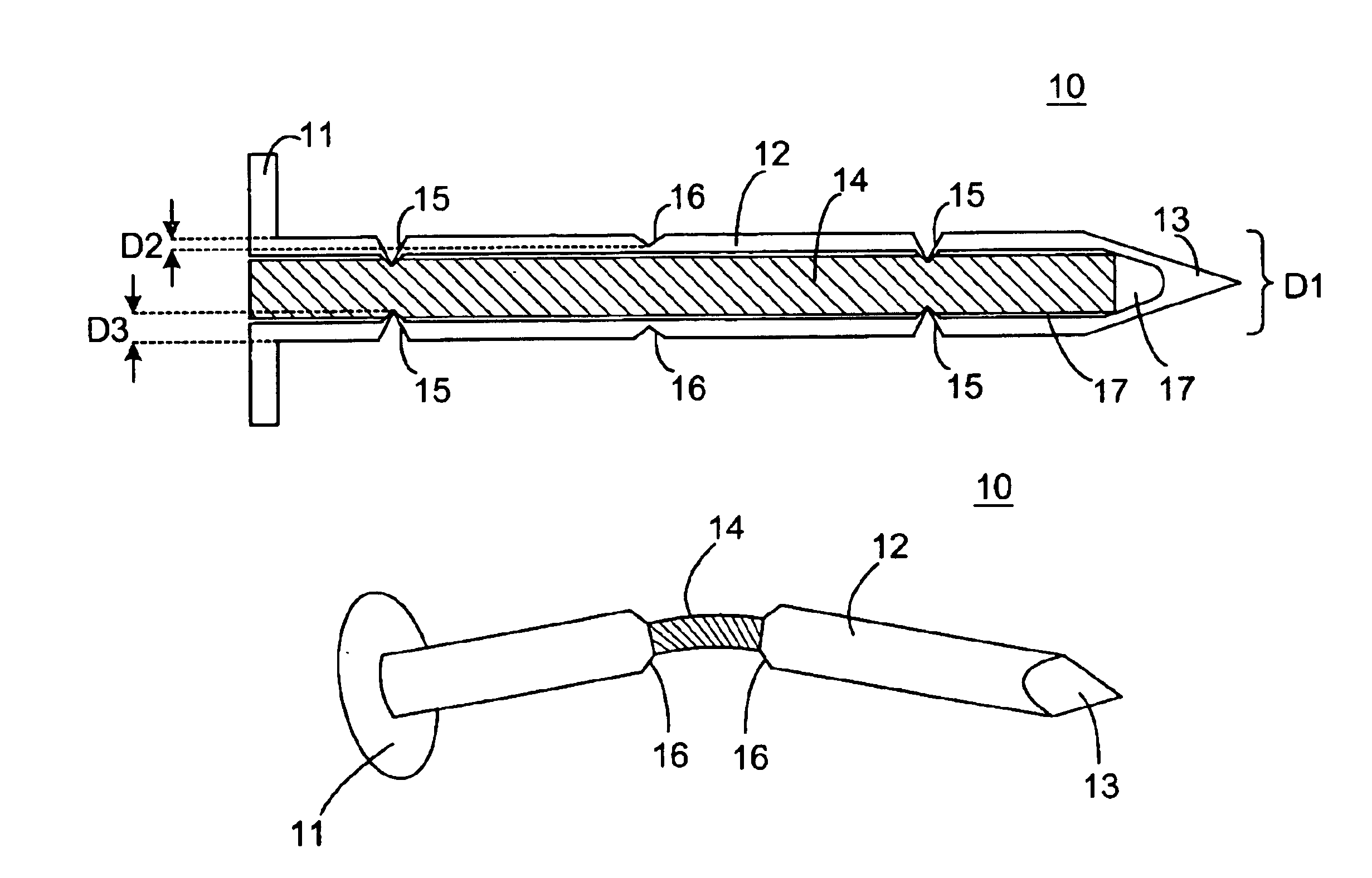
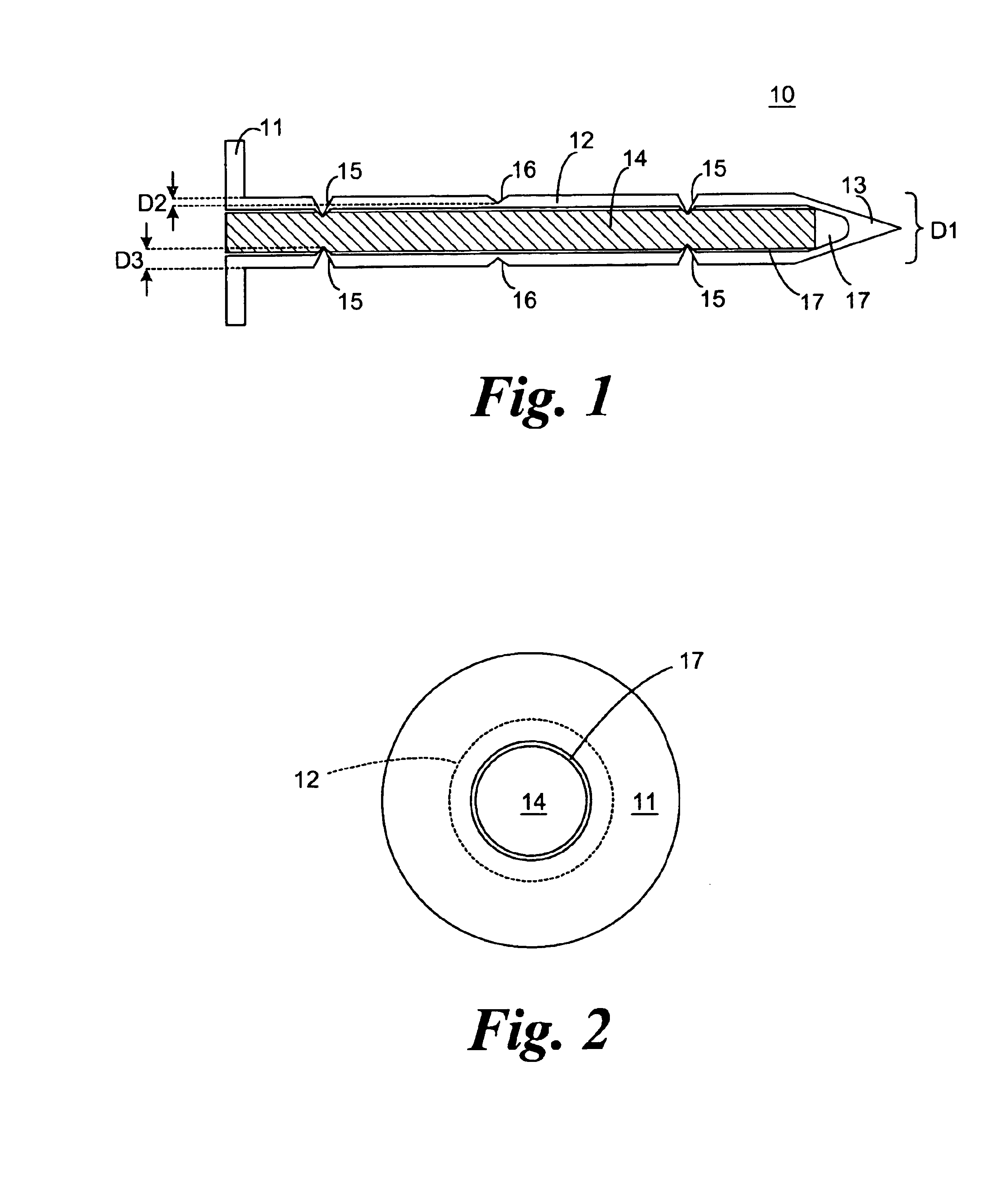
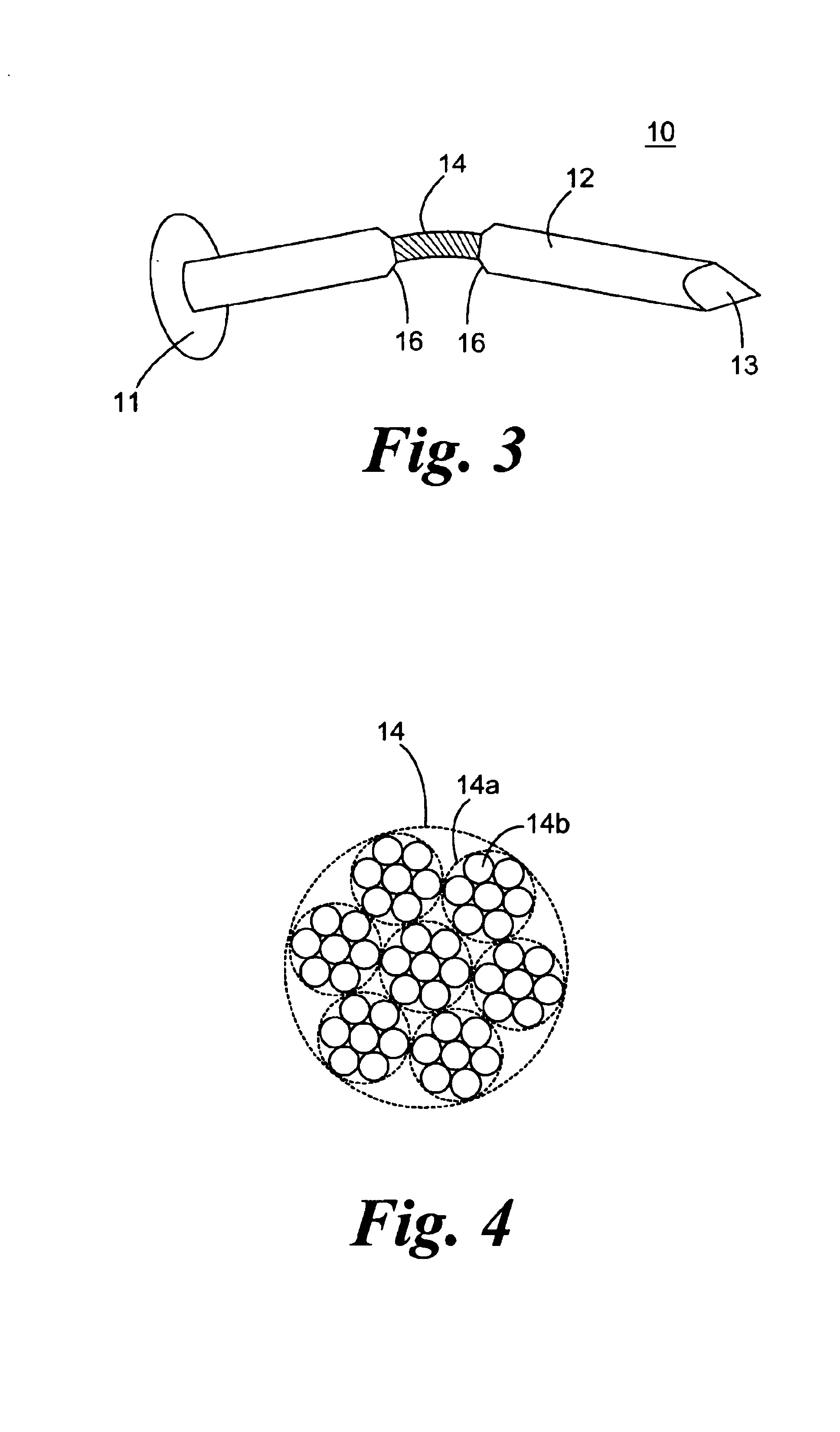
[0033]It is to be understood that the figures and descriptions of the present invention may have been simplified to illustrate elements that are relevant for a clear understanding of the present invention, while eliminating, for purposes of clarity, other elements found in a typical fastener. Those of ordinary skill in the art will recognize that other elements may be desirable and / or required in order to implement the present invention. However, because such elements are well known in the art, and because they do not facilitate a better understanding of the present invention, a discussion of such elements is not provided herein. It is also to be understood that the drawings included herewith only provide diagrammatic representations of the presently preferred structures of the present invention and that structures falling within the scope of the present invention may include structures different than those shown in the drawings. Reference will now be made to the drawings wherein li...


PUM


Abstract

A fastener, such as a nail, screw, etc., which possesses supplemental support and/or retention capability is provided. The fastener includes an elongated auxiliary member secured interiorly to, exteriorly to, or along the shaft of the fastener. The auxiliary member is secured to the shaft at two or more portions of the shaft. The auxiliary member provides the shaft with additional support strength and/or enables fastened materials to be retained upon breakage or shearing of the shaft as a result of, for example, heavy tensile or shearing loads. To facilitate breakage or shearing of the shaft, the shaft may be provided with a deformation, such as a notch or reduced circumference, at one or more desired locations such that the shaft breaks or shears at the deformation(s), thereby allowing the auxiliary member to function as the sole member which retains the fastened materials. The auxiliary member may be sufficiently flexible and pliable such that, upon breakage or shearing of the shaft, retention of the materials is maintained but in a less stressed form.

Description

FIELD OF THE INVENTION[0001]The present invention relates generally to the field of fasteners. In particular, the present invention relates to fasteners which possess supplemental support and retention capabilities. More specifically, the present invention relates to fasteners which possess supplemental support, and which possess retention capabilities upon breakage of the fastener shaft, by utilizing an elongated auxiliary member secured interiorly or exteriorly to the shaft, or along the shaft.BACKGROUND OF THE INVENTION[0002]In various instances, a fastener, e.g. a nail or screw, has been used to hold a material in place, such as house siding, shingles, sheathing, panels, structural members, etc., or to fasten studs, joists, beams, etc. In most cases, keeping materials fastened together is the sole goal and purpose of the fastener. However, in regions subject to windy conditions and / or earthquakes, these fasteners may fail to perform their sole function which sometimes results in...

Claims


Application Information

Patent Timeline
IPC IPC(8): F16B15/00F16B35/04
CPCF16B15/00F16B35/041Y10S411/901
Inventor NELSON, CHARLESESSERMAN, MATTHEW J.SCHNEIDER, JAMES E.
Owner NELSON CHARLES
Why Eureka
Try Eureka