Multi-bladed rotary cutting deck with mulching and discharge/collection modes

a rotary cutting deck and mulching technology, applied in the direction of mowers, agriculture tools and machines, etc., can solve the problems of easy loss or misplacement of mulching plugs, difficult to convert rotary cutting decks to mulching mode by manually inserting plugs into exit tunnels,

Inactive Publication Date: 2005-06-28
TORO CO THE
View PDF31 Cites 29 Cited by
  • Summary
  • Abstract
  • Description
  • Claims
  • Application Information

AI Technical Summary

Benefits of technology

[0007]One aspect of this invention relates to a rotary cutting deck for a mower which comprises a cutting deck having side-by-side cutting chambers. A cutting blade is contained in each cutting chamber. Each cutting blade is rotatable about a substantially vertical axis in a horizontal cutting plane to cut grass and create grass clippings. The grass clippings created by the cutting blades are directed longitudinally on the cutting deck between the rotational axes of the cutting blades. A longitudinally extending exit tunnel is located on the cutting deck between the rotational axes of the cutting blades in a position to intercept the grass clippings created by the cutting blades. A pivotal mulch door is located inside the exit tunnel for pivotal movement between a first position in which the exit tunnel is open and a second position in which the exit tunnel is closed, whereby the exit tunnel can be open in the first position of the mulch door to provide a discharge / collection mode of operation or can be closed in the second position of the mulch door to provide a mulching mode of operation.

Problems solved by technology

This can be difficult to do given the placement of the cutting deck relative to the rest of the mower and given the fact that the exit tunnel is in the center of the deck along a rear side of the deck and is not at the side of the deck.
Thus, converting the rotary cutting deck to the mulching mode by manually inserting a plug into the exit tunnel is not as easy as would be desirable.
This is obviously a disadvantage of a system that requires a separate mulching plug to convert the rotary cutting deck to the mulching mode.
In addition, the mulching plug is prone to being lost or misplaced.
If this happens, the operator cannot convert the rotary cutting deck to the mulching mode without finding or replacing the mulching plug.
Again, this can be inconvenient and annoying.

Method used


Image

  • Multi-bladed rotary cutting deck with mulching and discharge/collection modes
  • Multi-bladed rotary cutting deck with mulching and discharge/collection modes
  • Multi-bladed rotary cutting deck with mulching and discharge/collection modes

Examples


Embodiment Construction

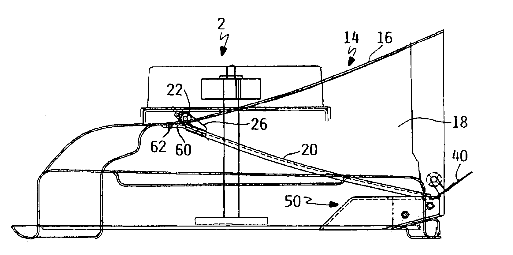
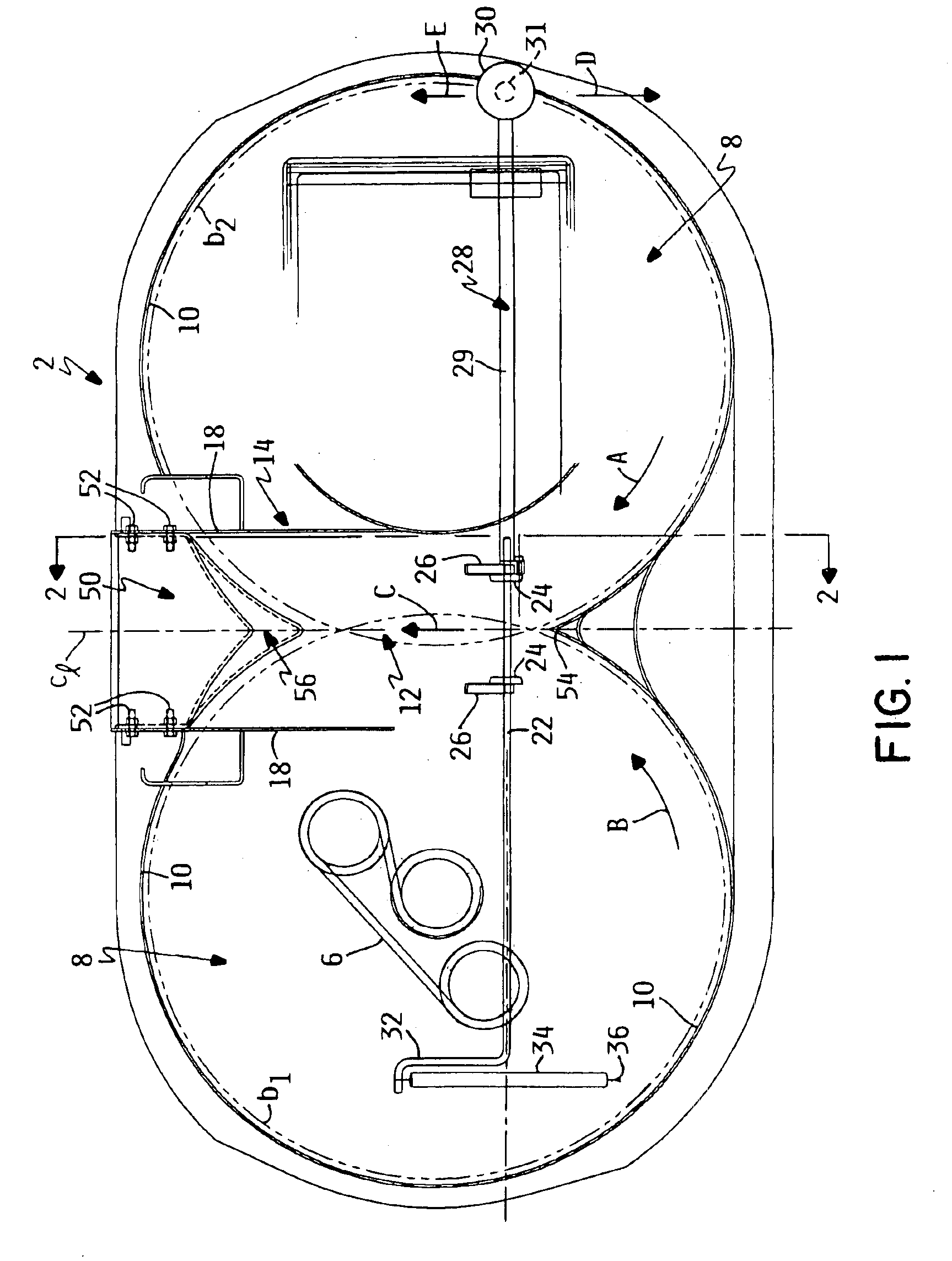
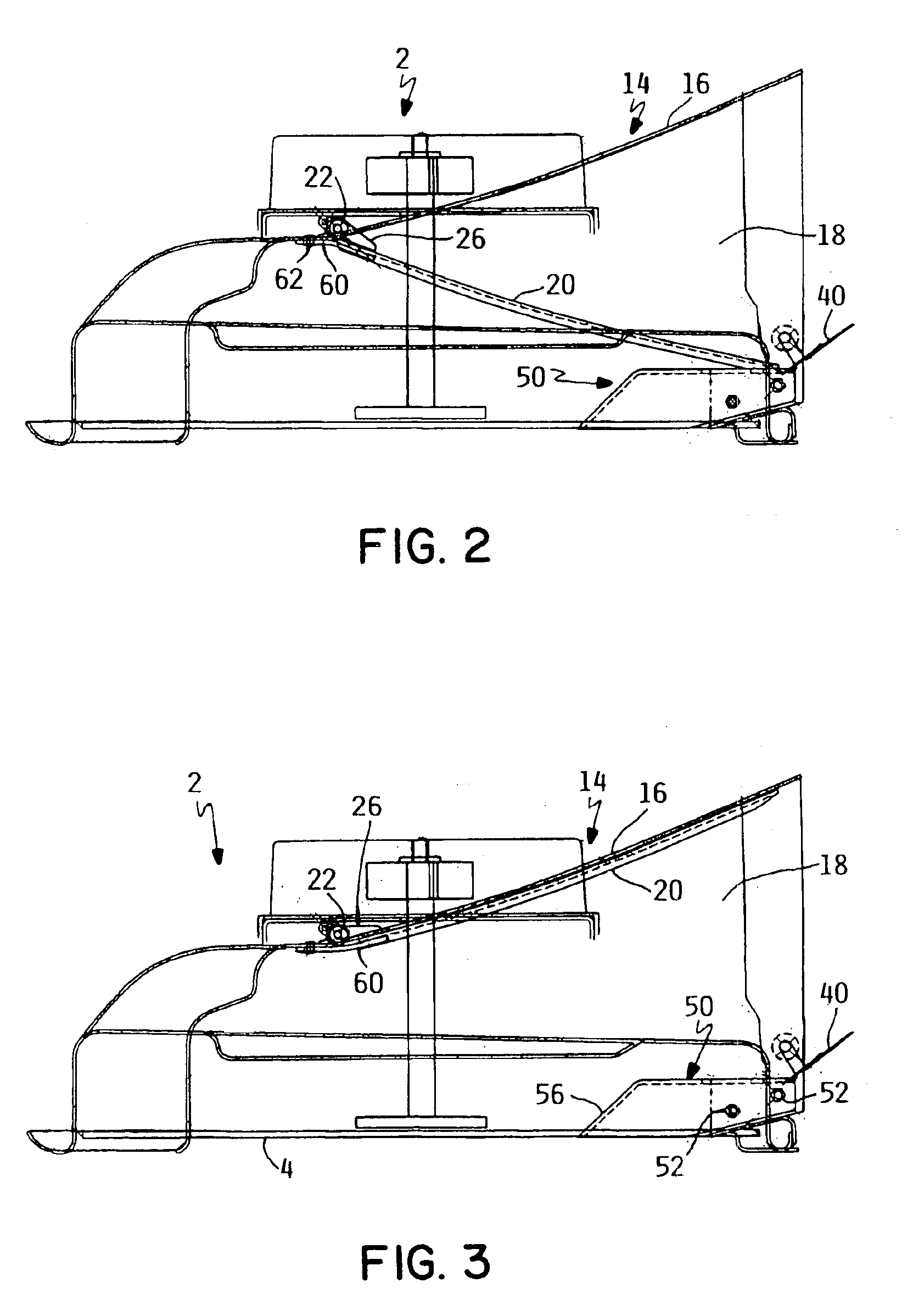
[0015]A rotary cutting deck according to this invention is illustrated generally as 2. Rotary cutting deck 2 is so named because the grass is cut by multiple cutting blades 4 each of which rotates in horizontal cutting planes. One such cutting blade 4 is shown in FIG. 2.

[0016]The orbits of the tips of cutting blades 4 are indicated in FIG. 1 as b1 and b2. Because blade orbits b1 and b2 intersect over the centerline c1 of rotary cutting deck 2, cutting blades 4 are timed in their rotation so as not to hit one another. For example, cutting blades 4 are rotated by a belt drive system 6, a portion of which is shown in FIG. 1, utilizing a cogged timing belt or the like.

[0017]Each cutting blade 4 has sharpened cutting edges (not shown) which sever uncut grass as cutting blades 4 are rotated in their horizontal cutting planes. The height of cut can be adjusted by changing the vertical height of rotary cutting deck 2 above the ground in ways that are well known in the grass mowing art.

[0018...


PUM


Abstract

A rotary cutting deck has dual, side-by-side cutting chambers each of which houses a rotary cutting blade. The blades rotate so that grass clippings exit to the rear of the cutting deck through a central, rearwardly extending exit tunnel. A pivotal mulch door is located within the exit tunnel with the mulch door swinging between two positions. In one position, the exit tunnel is open to permit operation of the cutting deck in a discharge/collection mode of operation. In the other position, the exit tunnel is closed to convert the cutting deck to a mulching mode of operation. A V-shaped baffle with a forwardly facing apex is placed in the bottom and rear of the exit tunnel to enhance performance in the mulching mode of operation.

Description

TECHNICAL FIELD[0001]This invention relates to a multi-bladed rotary cutting deck which is convertible between mulching and discharge / collection modes of operation.BACKGROUND OF THE INVENTION[0002]Multi-bladed rotary cutting decks are known which have dual, side-by-side cutting chambers. Each cutting chamber encloses a cutting blade that is rotatable about a substantially vertical axis such that the cutting blade rotates in a substantially horizontal cutting plane. The blades rotate oppositely to one another such that the grass clippings generated by each cutting blade merge together into a common grass clipping stream. A rearwardly extending and rearwardly opening exit tunnel on the cutting deck receives this grass clipping stream to allow the stream to exit to the rear of the cutting deck, either for discharge onto the ground or for collection in a grass bagging apparatus. Thus, the cutting deck has a first discharge / collection mode of operation when the exit tunnel is open and pe...

Claims


Application Information

Patent Timeline
Patent Type & Authority Patents(United States)
IPC IPC(8): A01D34/63A01D42/00A01D34/71
CPCA01D34/71A01D42/005A01D2101/00
Inventor KAKUK, JAY J.
Owner TORO CO THE
Why Eureka
Try Eureka