
Dropped deck center beam rail road car

a technology of center beam and rail road car, which is applied in the direction of wagons/vans, tank wagons, wagons, etc., can solve the problems of plastic sheeting being prone to damage, innermost, uppermost boards can be damaged, and the innermost may tend to be torn or damaged

Inactive Publication Date: 2005-07-26
NATIONAL STEEL CAR
View PDF125 Cites 10 Cited by
  • Summary
  • Abstract
  • Description
  • Claims
  • Application Information

AI Technical Summary

Benefits of technology

[0020]In an aspect of the invention there is a center beam railroad car having a longitudinal centerline. The railroad car is supported by rail car trucks at either end thereof. The railroad car comprises a cargo support structure borne between the trucks, upon which cargo can be carried. There is a web work assembly including an array of posts mounted along the longitudinal centerline of the rail road car. The array extends upwardly of the cargo support structure, and the array is braced longitudinally. An upper beam assembly surmounts the web work assembly. The upper beam assembly has cantilevered wings extending laterally of t...

Problems solved by technology

As the car travels, it is subject to vibration and longitudinal inertia loads.
Consequently the plastic sheeting may tend to be torn or damaged in the vicinity of the vertical posts, and the innermost, uppermost boards can be damaged.
The physical damage to these boards may tend to make them less readily saleable.
Further, whether or not the boards are damaged, if the plastic is ripped, moisture can collect inside the sheeting.
This may lead to the growth of molds, and may cause discolouration of the boards.
In part, the difficulty arises because the bearing area may be too small.
Further still, when the posts are fabricated the flanges may not stand perfectly perpendicular to the web, such that one edge of the flange may bear harder against the bundles than another.
Although it is possible to use wooden battens at the top end of the center beam web, this will tend to cause the top bundle to sit outwardly of its neighbours.
It has been observed that a thin wooden batten, of ¾″ thickness may tend to bow inwardly between adjacent posts, and may not spread the wear load as much as may be desired.
However, the space available for employing a batten may tend to be limited by the design envelope of the car.
Wooden battens may also be prone to rotting if subject to excessive exposure to moisture, or may be consumable wear items that may require relatively frequent periodic replacement.
In general, however, the height of the shear plate, or top flange of the bolster, to the well decking is less than the desired 33 inch bundle height.

Method used


Image

  • Dropped deck center beam rail road car
  • Dropped deck center beam rail road car
  • Dropped deck center beam rail road car

Examples


Embodiment Construction

[0095]The description which follows, and the embodiments described therein, are provided by way of illustration of an example, or examples of particular embodiments of the principles of the present invention. These examples are provided for the purposes of explanation, and not of limitation, of those principles and of the invention. In the description which follows, like parts are marked throughout the specification and the drawings with the same respective reference numerals. The drawings are not necessarily to scale and in some instances proportions may have been exaggerated in order more clearly to depict certain features of the invention.

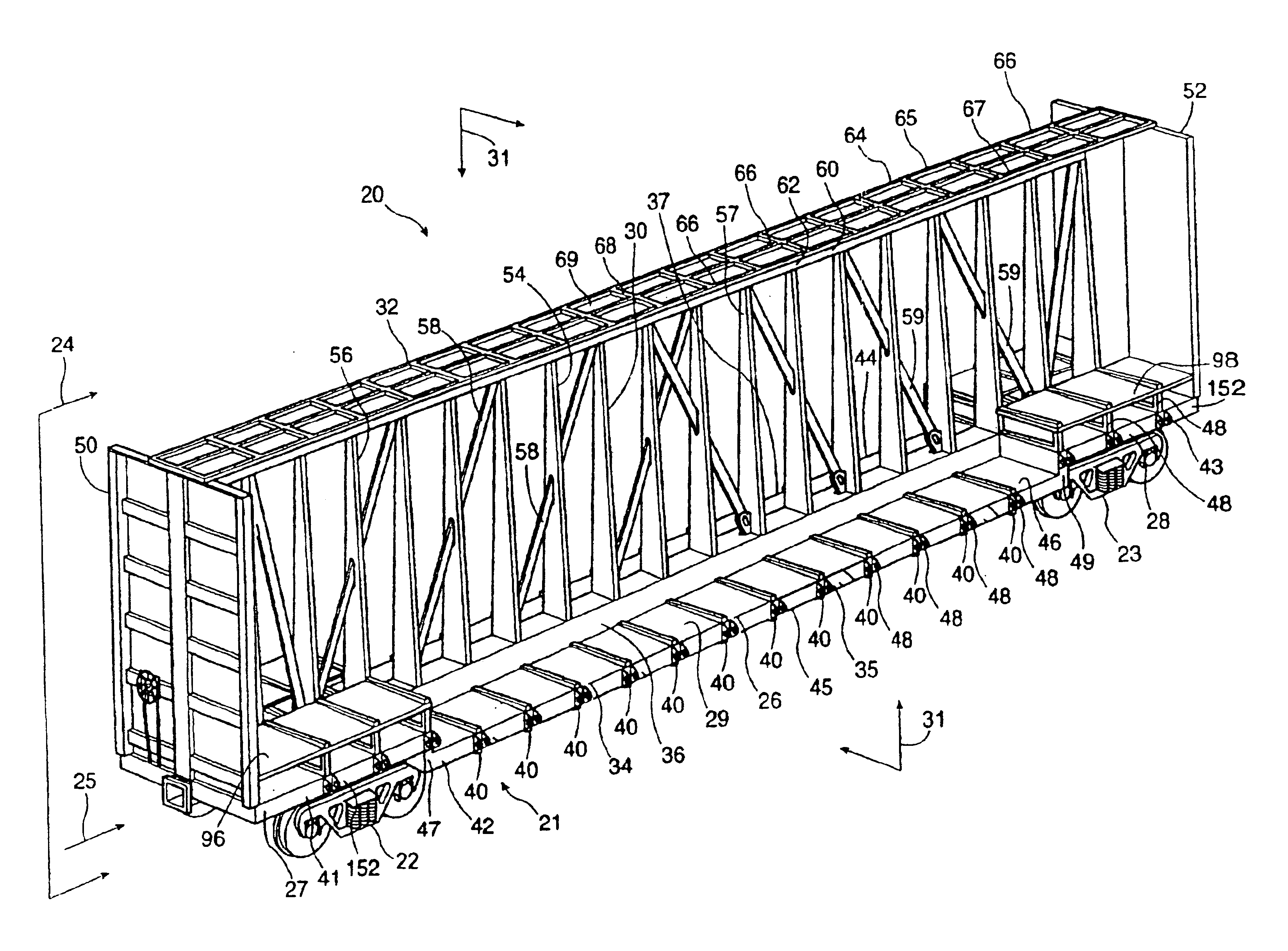
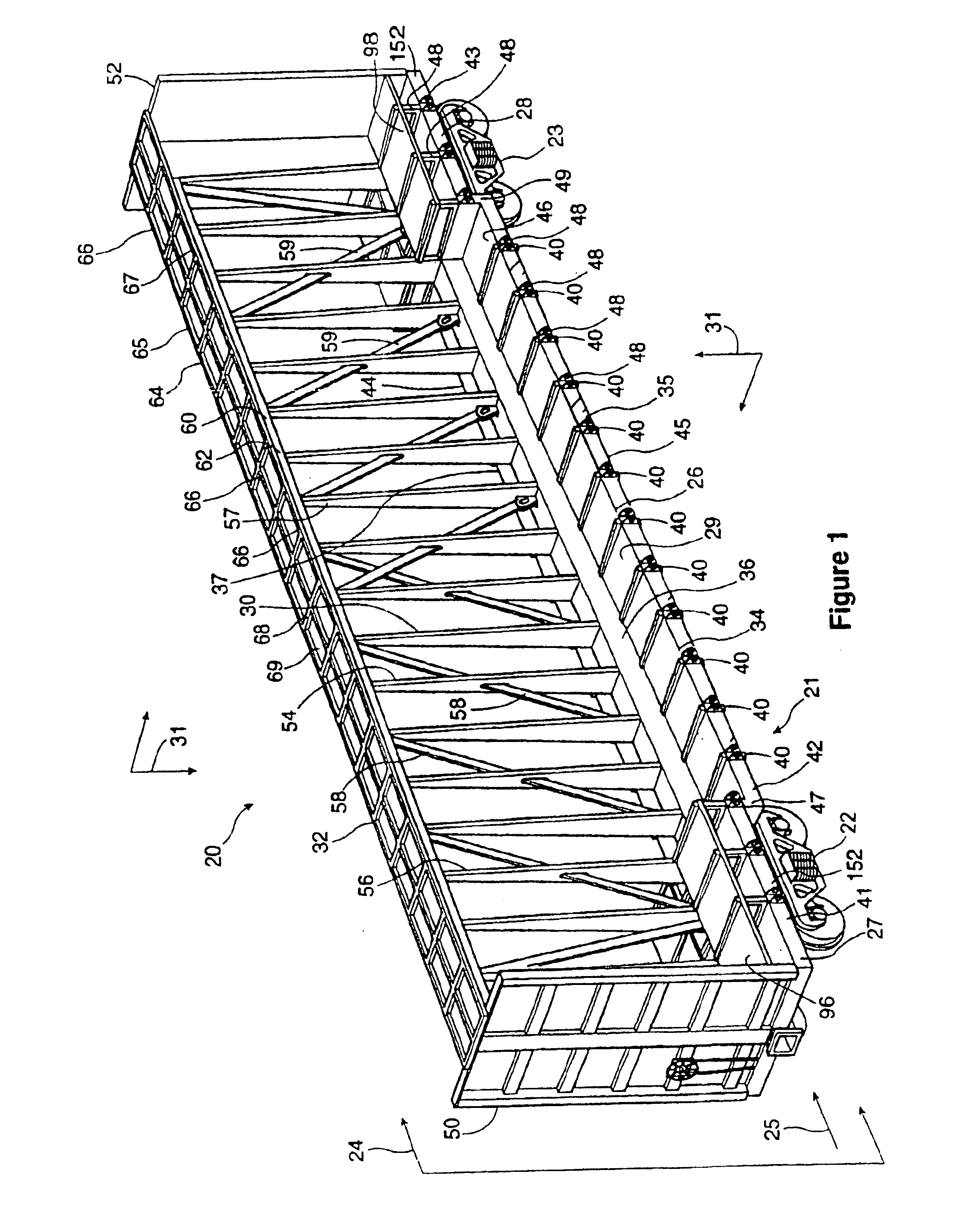
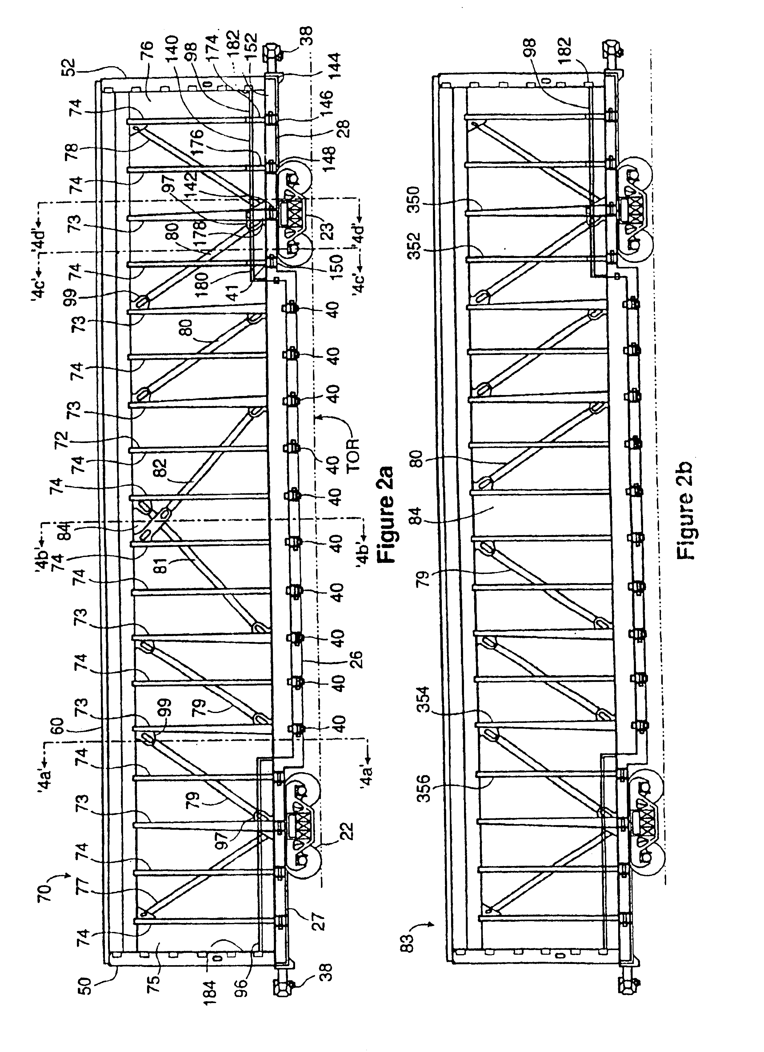
[0096]A center beam railroad car is indicated in FIG. 1 generally as 20. It has a center beam rail road car body 21 carried on a pair of longitudinally spaced apart railroad car trucks 22 and 23 and operable to roll in a rolling, direction along rails in the generally understood manner of rail cars. Car 20 has a longitudinal centerline 25 lying ...


PUM


Abstract

A center beam car has a main deck structure extending laterally from a main center sill, a laterally extending top truss structure, and a central vertically oriented web work structure for carrying vertical shear loads between the top truss and the center sill and decking. The center beam so formed defines bunks upon in which to carry cargo. The upper region of the web-work structure includes a deep upper beam structure that has downwardly extending skirts. The skirts provide an extended bearing area upon against which bundled loads can be secured. The skirts are inwardly reinforced to discourage deflection between adjacent upright members of the deep upper beam structure.

Description

[0001]This application is a continuation of U.S. patent application Ser. No. 09 / 705,056, filed Nov. 2, 2002 and now abandoned.FIELD OF THE INVENTION[0002]This invention relates generally to center beam rail road cars, and, in particular, to center beam cars having a depressed deck portion between a pair of rail car trucks.BACKGROUND OF THE INVENTION[0003]Center beam rail road cars, in cross-section, generally have a rack-like body, namely a center beam structure in the shape of an I in which the top flange is narrower than the bottom flange. The center beam structure is carried on a pair of rail car trucks. The rack, or center beam structure, has a pair of bulkheads at either longitudinal end that extend transversely to the rolling direction of the car. The lading supporting structure of the beam includes laterally extending decking mounted above, and spanning the space between, the trucks. A center beam web structure, typically in the nature of an open frame truss for carrying vert...

Claims


Application Information

Patent Timeline
IPC IPC(8): B61D3/00B61D3/08B61D3/16
CPCB61D3/08B61D3/16
Inventor FORBES, JAMES W.KHATTAB, MOHAMED A.WILSON, ALISTAIR
Owner NATIONAL STEEL CAR
Learn More