Axial flux motor assembly

a technology of axial flux and motor assembly, which is applied in the direction of magnetic circuit rotating parts, magnetic circuit shape/form/construction, cycle equipment, etc., can solve the problems of increasing assembly cost and weight, and assembly is less compa

Inactive Publication Date: 2005-07-26
THE TIMKEN CO
View PDF30 Cites 53 Cited by
  • Summary
  • Abstract
  • Description
  • Claims
  • Application Information

AI Technical Summary

Benefits of technology

[0005]Briefly stated, the present invention provides an assembly comprising a pair of electric motors and a pair of speed reduction transmissions within a single electric motor case and a driveline support. Each electric motor comprises a stator and a rotor, wherein the rotor is connected to a rotor shaft. A rotor support bearing rotatingly supports each rotor shaft. A driveline support supports a pair of hubs rotatably attached to the housing by a bearing. A case is attached to the housing and supports each stator and an associated speed reduction transmission. Each s

Problems solved by technology

However, using separate bearings only adds the cost and weigh

Method used


Image

  • Axial flux motor assembly
  • Axial flux motor assembly
  • Axial flux motor assembly

Examples


embodiment 100

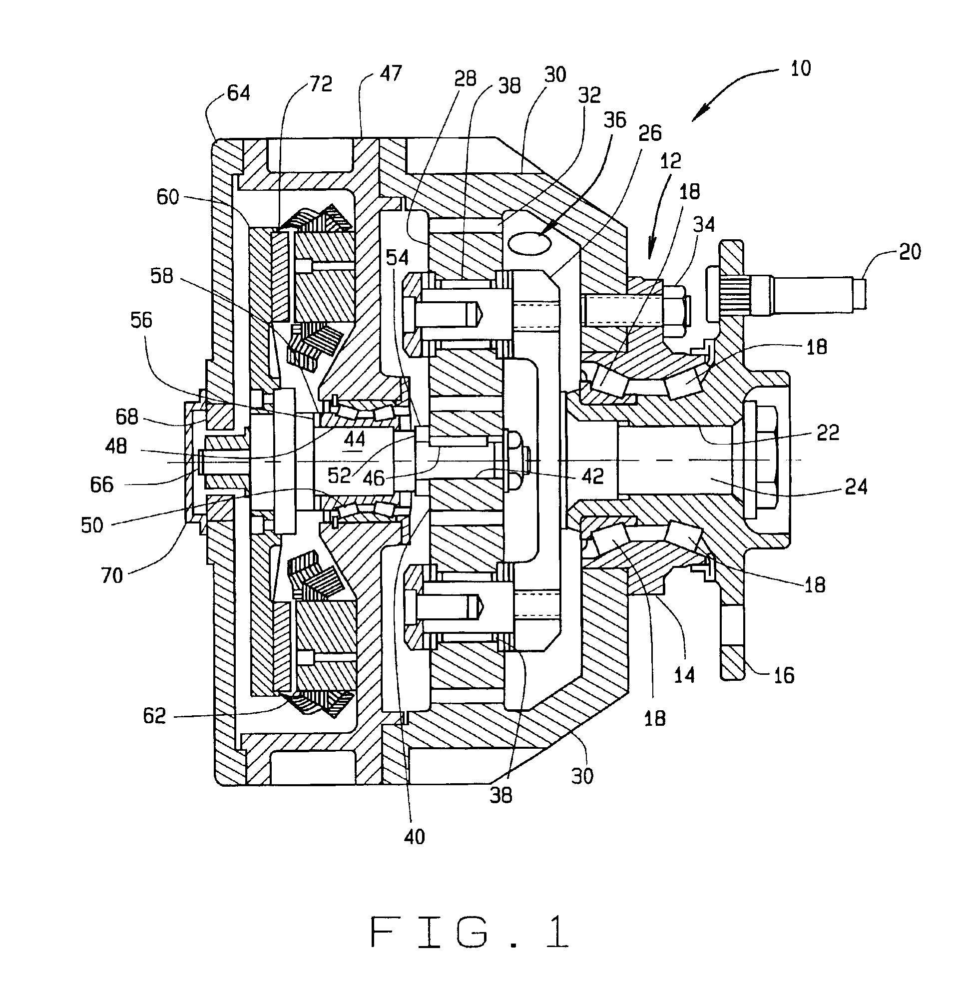
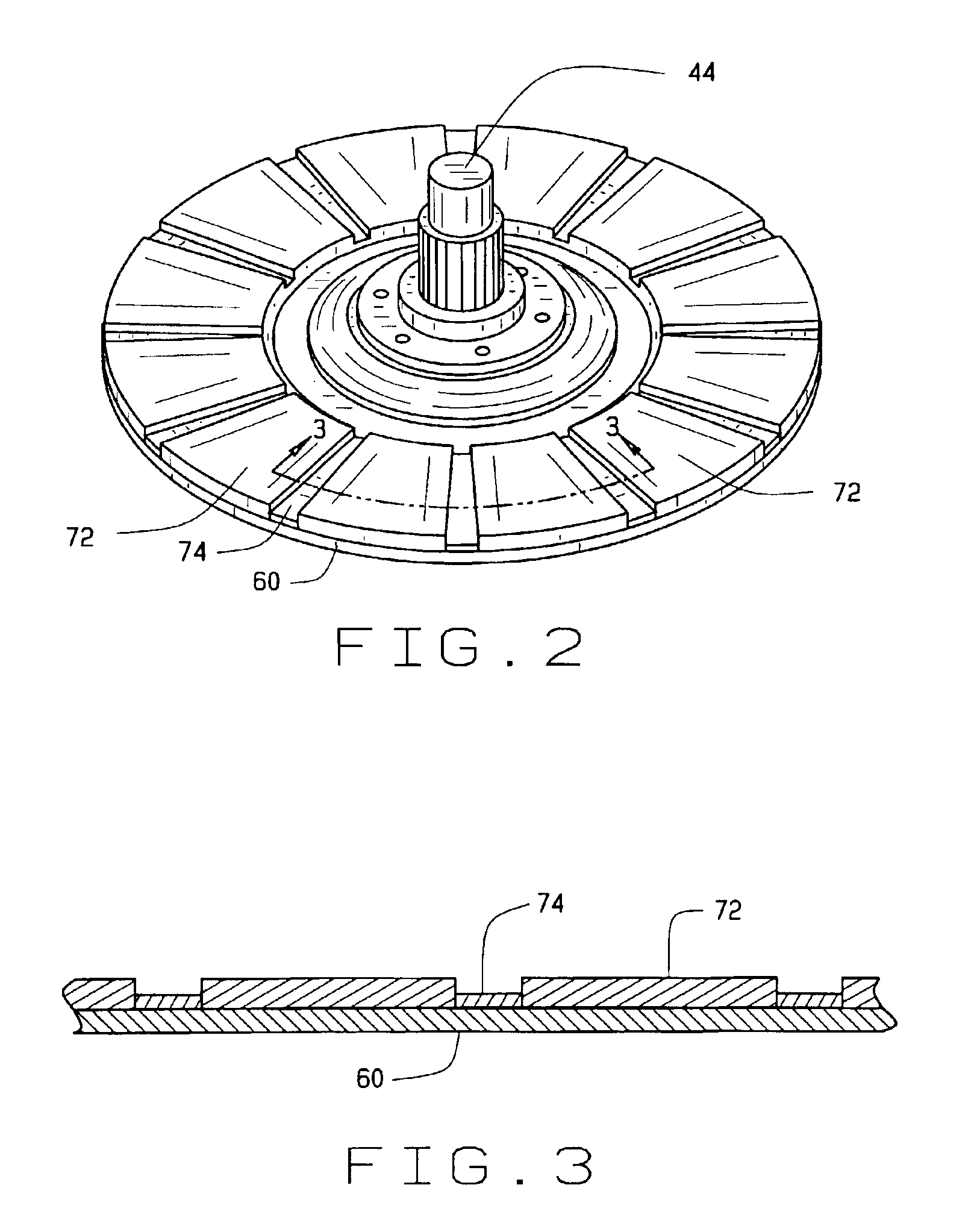
[0028]An alternate embodiment 100 shown in FIG. 6 includes a rotor 132 having magnets 134 affixed to opposite sides of the rotor 132 by an adhesive. Adjacent magnets 134 on opposite sides of the rotor 132 are aligned so that their opposite poles face outwardly from the rotor 132. In addition to the stator 62 and the windings 80 is a second stator 140 and a second plurality of windings 144 wound within the second stator 140. By adding the second stator 140 and windings 144, the output of the axial flux motor is nearly doubled.

embodiment 200

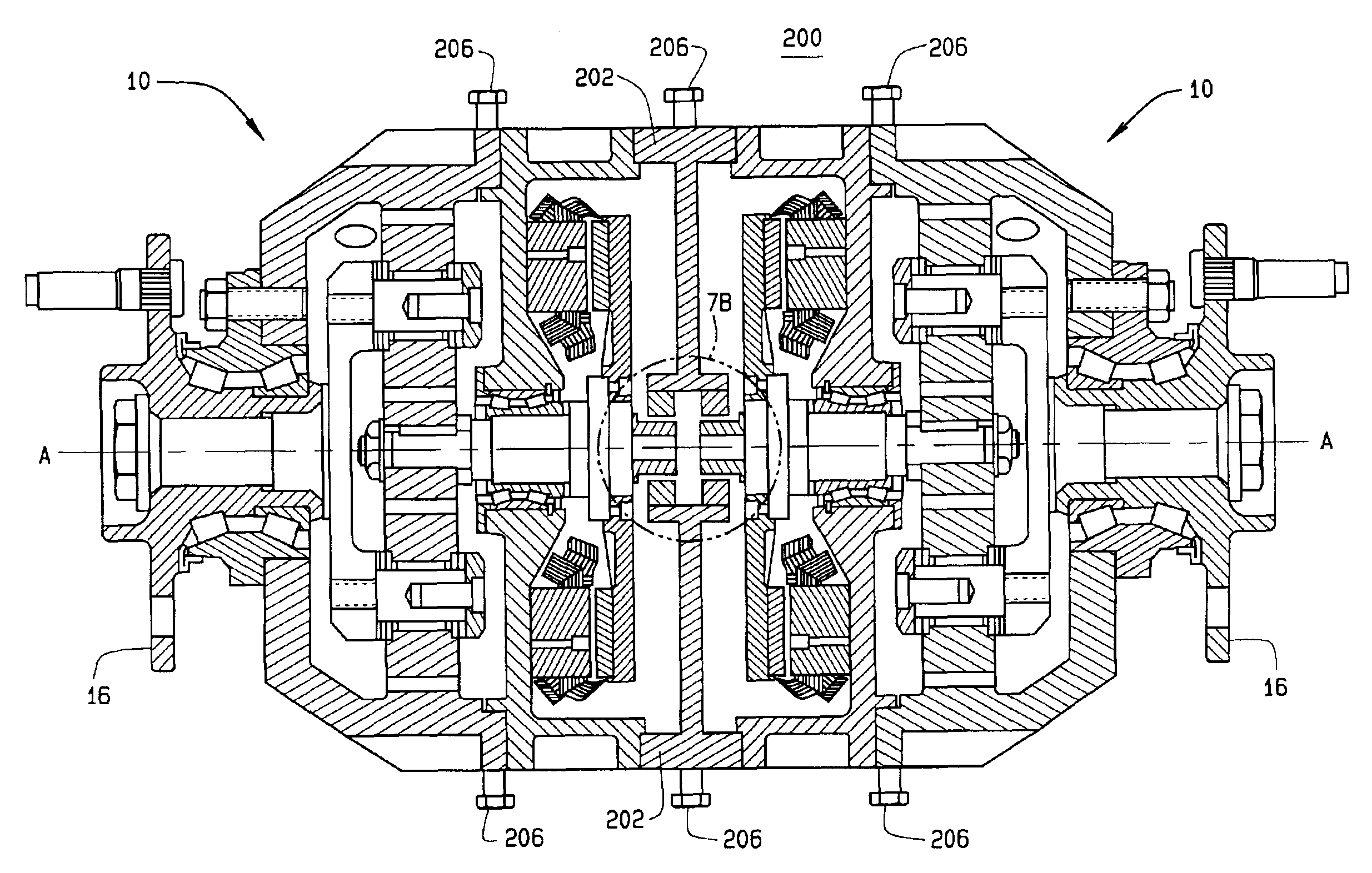
[0029]In a compact power unit embodiment 200, shown in FIGS. 7A and 8A, a pair of axial flux motor assemblies 10 or axial flux motor assemblies 100, as described in detail above, are coupled together in mirrored or back-to-back alignment with a common end plate 202. The common end plate 202 includes an axial bore 204, shown in FIGS. 7B and 8B for supporting a pair of resolvers 68 and for receiving the rotor shaft extension 66 from each rotor shaft 44 in the compact power unit 200. Stator cooling connections 206 are secured to each motor case 47 to carry out heat generated by the windings 80 during heavy duty cycles.

[0030]The compact power unit 200 provides two identical independent output hubs 16, having a common axis of rotation A—A, onto which a pair of drive axles or wheels (not shown) may be secured. The compact power unit 200 is suitable for mounting at an axle centerline of a vehicle to drive either directly or indirectly, a pair of vehicle wheels on opposite sides of the vehi...


PUM


Abstract

A power unit assembly which has a pair of mirrored axial flux electric motors having a common axis of rotation, each axial flux motor including a rotor disposed on a rotor shaft and at least one stator disposed in operative relationship to said rotor. A common end plate is disposed between each of the pair of axial flux electric motors to provide a common mounting structure, while an output hub is operatively coupled to each rotor shaft of the pair of mirrored axial flux electric motors. Each of the pair of mirrored axial flux electric motors is operatively configured to provide independent speed and torque to each associated output hub.

Description

CROSS-REFERENCE TO RELATED APPLICATIONS[0001]The present application is a continuation-in-part of U.S. patent application Ser. No. 10 / 116,974, filed on Apr. 5, 2002, now abandoned from which priority is claimed.STATEMENT REGARDING FEDERALLY SPONSORED RESEARCH[0002]Not Applicable.BACKGROUND OF THE INVENTION[0003]The present invention relates generally to a vehicle driveline support assembly and, more particularly, to a vehicle driveline support assembly incorporating a pair of electric motors wherein the driveline support, the pair of electric motors, and a pair of speed reduction transmissions are combined into a single compact power unit with two independent co-axial output shafts which may be independently controlled for speed and torque.[0004]A variety of driveline support assemblies are known in the art that utilize electric motors to power a driveline or vehicle wheel when accelerating or maintaining driveline motion, or to generate electricity from the driveline's kinetic ener...

Claims


Application Information

Patent Timeline
IPC IPC(8): H02K7/116H02K16/00H02K21/12H02K21/24H02K5/173H02K11/00
CPCH02K7/116H02K16/00H02K21/24H02K5/1735H02K11/00
Inventor HASHIMOTO, FUKUOZHOU, RAO-SHENGGRADU, MIRCEA
Owner THE TIMKEN CO
Why Eureka
Try Eureka