Swing arm guidance system

a technology of swing arm and guidance system, which is applied in direction finders using radio waves, navigation instruments, instruments, etc., can solve the problems of circular water pattern, decreased production or complete loss of production therein, and end guns not being effective or efficient methods, etc., to achieve the effect of improving the system operation

Active Publication Date: 2005-08-02
REINKE MFG
View PDF10 Cites 42 Cited by
  • Summary
  • Abstract
  • Description
  • Claims
  • Application Information

AI Technical Summary

Benefits of technology

[0014]In the preferred embodiment an antenna of the swing arm receiving means is mounted in a position forward of one of the steerable wheels of the swing tower and is adapted to pivot in a direct relation to the pivoting of the wheels to improve the operation of the system.

Problems solved by technology

They suffer from the deficiency that they produce a circular water pattern, although most fields are either rectangular or square shaped.
Accordingly, a center pivot system by itself will not be able to provide water to the corners of a field, resulting in decreased production or complete loss of production therein.
Due to this fact, end guns are not an effective or efficient method for watering the corners and improved corner watering systems have been desired.
Nevertheless, there are certain drawbacks in such systems, particularly in instances where the topsoil of a field may overlie a rock substrata.
In view of the fact that a buried cable system requires the laying of ten thousand or more feet of cable, when rock is present in a field, installation of the buried cable becomes unusually difficult and expensive.
It is also very expensive to repair or to alter the path of the system once the cable is buried.
Until recently the use of Global Positioning Satellite (GPS) data to guide the swing arm of a center pivot irrigation system would have been impractical from the standpoint that such position calculations were too inaccurate and GPS receiver / senders were prohibitively expensive.
However, locating the swing tower receiving antenna in such position is detrimental to optimum guidance of the swing tower.

Method used


Image

  • Swing arm guidance system
  • Swing arm guidance system
  • Swing arm guidance system

Examples


Embodiment Construction

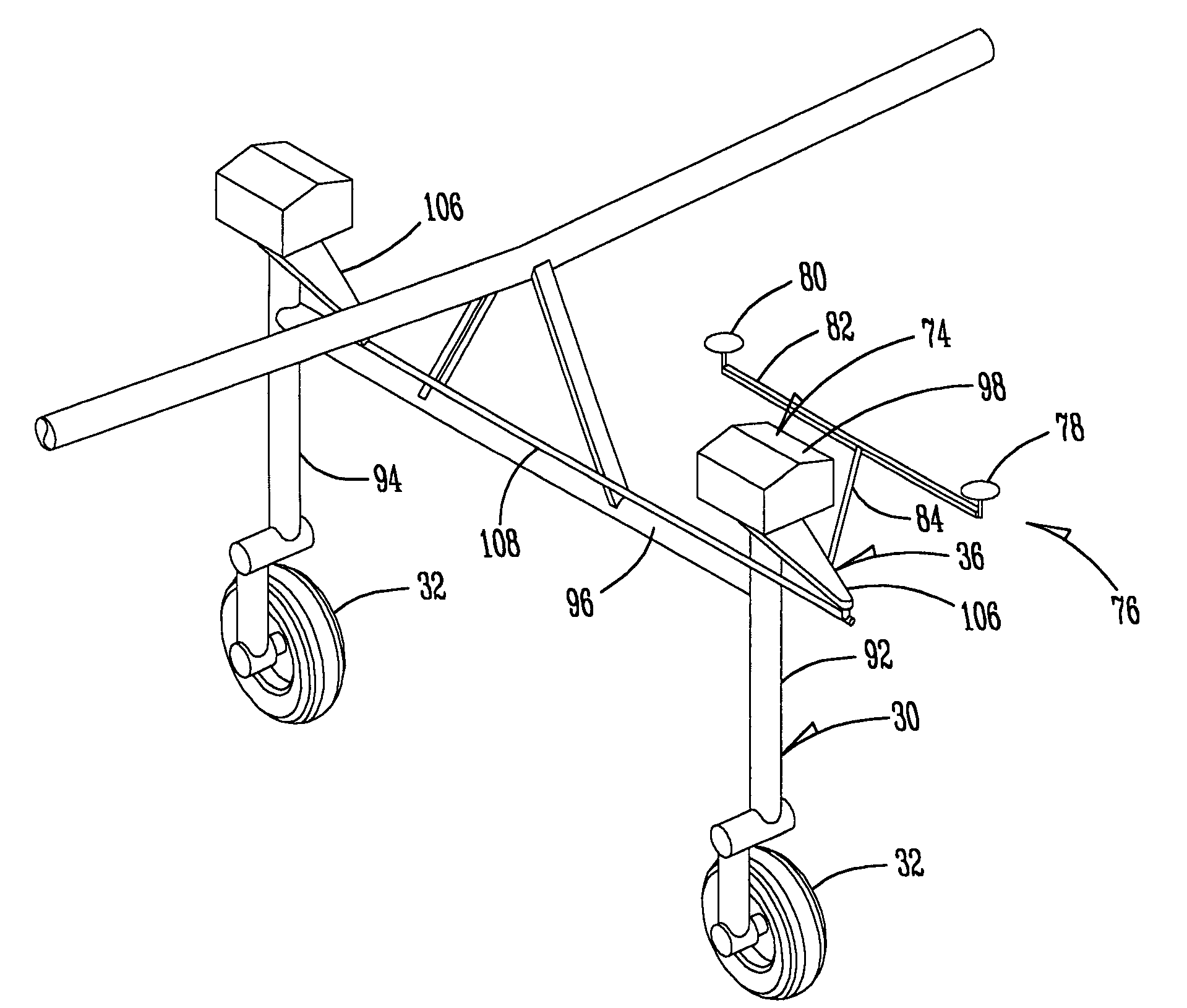
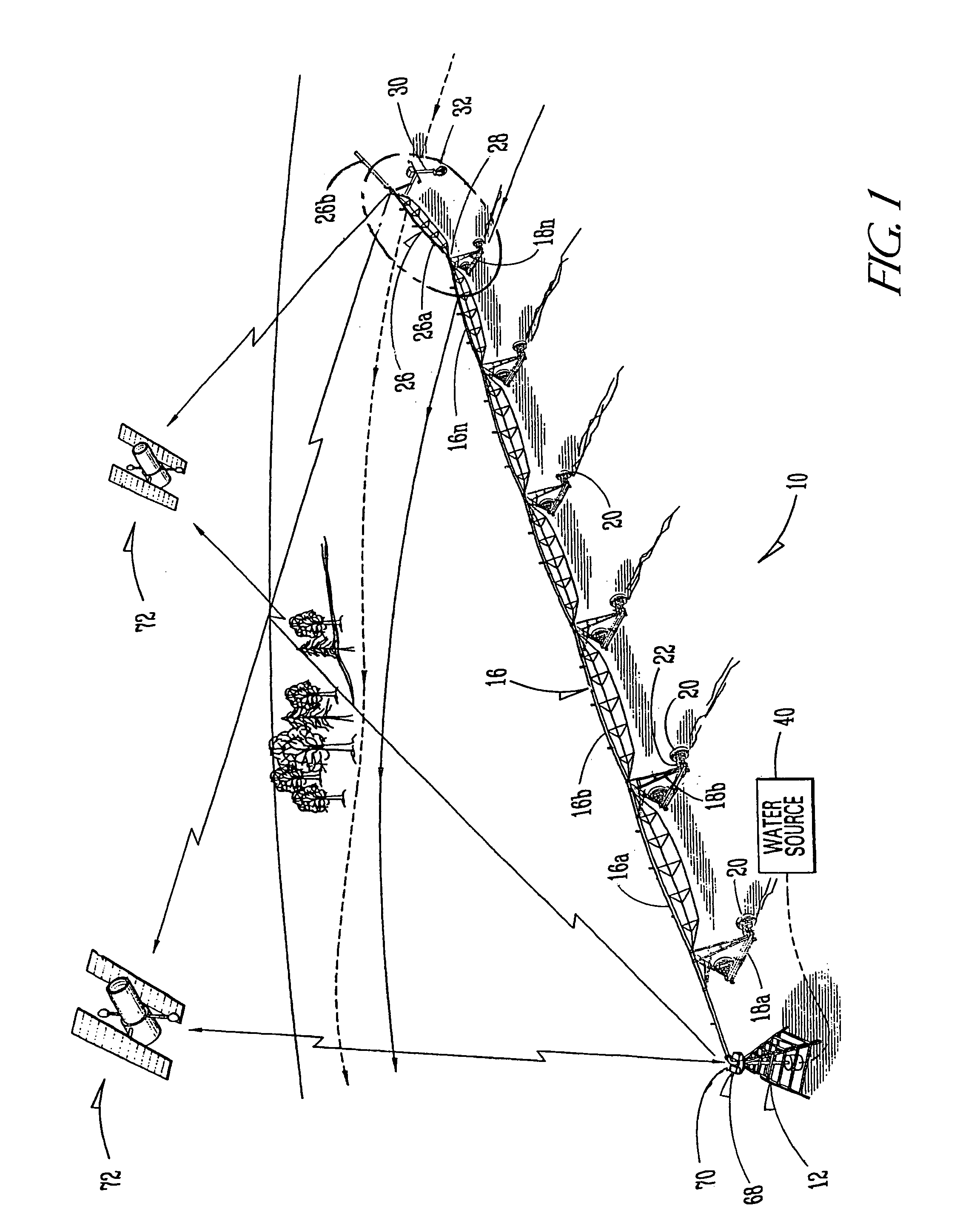
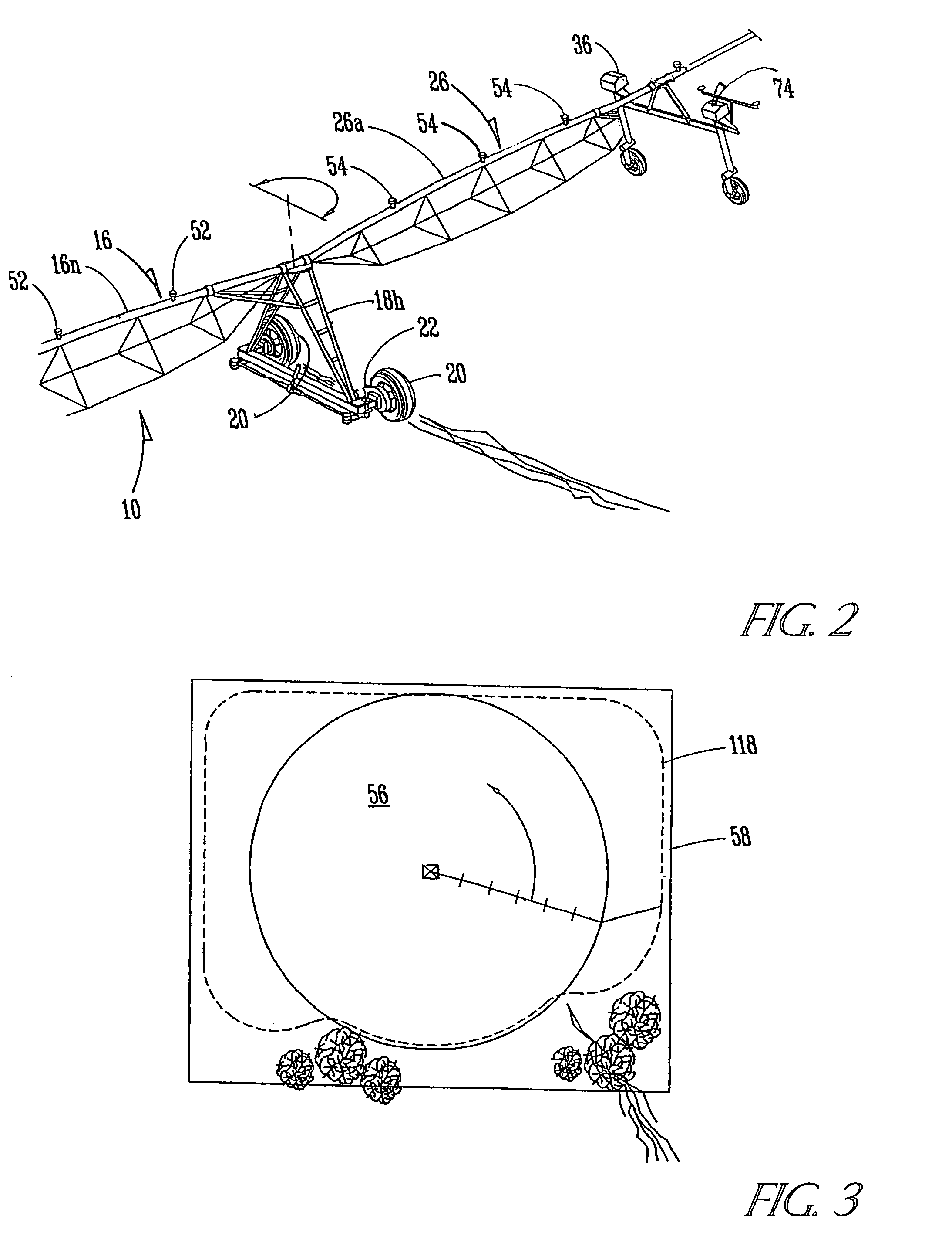
[0023]FIG. 1 shows a swing arm center pivot irrigation system generally at 10. A center pivot 12 for the system 10 is stationary and connected to a main boom 16 which can be comprised of several separate boom sections 16a, 16b . . . 16n. Such boom sections are supported by means of supporting towers 18a through 18n, each of which have wheels 20 and drive motors 22. A swing arm 26 (best shown in FIG. 2) is comprised of boom section 26a and 26b and is pivotally connected at 28 to the outer end of the boom section 16n. The swing arm 26 is supported by a swing tower 30 which has wheels 32 that are in a tandem relationship. The wheels 32 on the tower 30 are steerable by the use of steering means 36 (see FIGS. 2 and 4) and are driven by electric motors (not shown) in a response to movement of the main boom 16 with respect to the swing arm 26 as is well-known in the art.

[0024]The center pivot 12 is connected to a source of water, such as a well 40. Water is supplied from the well 40 along ...


PUM


Abstract

A guidance system for controlling the steering of a swing arm on a center pivot irrigation system is provided through the use of two satellite signal receiving antennas associated with a drive tower for the swing arm. The signal receiving antennas are mounted from the swing tower so that one of the antennas is in a position forwardly of a steerable wheel for the tower and the other antenna is located in a position rearwardly of the steerable wheel. The signal receiving antennas are mounted in such fashion that they rotate in a direct relation to the steering of the steerable wheel so as to provide position information for the steering of the drive tower that more efficiently and effectively maintains the drive tower on a desired path of travel.

Description

BACKGROUND OF THE INVENTION[0001]1. Field of the Invention[0002]The present invention relates in general to center pivot irrigation systems having swing arms for providing water to the corners of a field and more specifically relates to a guidance system that is utilized for controlling the travel of the swing arm on a desired path.[0003]2. Description of the Prior Art[0004]Center pivot irrigation systems have long been known in the art for providing water to large sections of land. A typical center pivot system is capable of irrigating one hundred and sixty acres or more. A center pivot system is formed of a main arm water conduit that is fixed at one end to a central point of water supply. The main arm is supported on a plurality of wheeled towers and is pivotally attached to the source of water to provide a circular irrigation pattern surrounding such supply.[0005]Center pivot irrigation systems have proven to be highly efficient in irrigating large sections of land. They suffer ...

Claims


Application Information

Patent Timeline
Patent Type & Authority Patents(United States)
IPC IPC(8): A01G25/09A01G25/00G01C21/00G05D1/02
CPCA01G25/092G01C21/005G05D1/0278G05D2201/0201
Inventor BARKER, LUKE J.
Owner REINKE MFG
Why Eureka
Try Eureka