Internal combustion engine with exhaust-gas turbocharging arrangement

a technology of internal combustion engine and turbocharging arrangement, which is applied in the direction of combustion engine, machine/engine, engine fuction, etc., can solve the problems of reducing output power, affecting efficiency, and observing noticeable torque drop, so as to reduce engine emissions, improve heat retention, and reduce the temperature increase of engine components

Active Publication Date: 2018-01-25
FORD GLOBAL TECH LLC
View PDF16 Cites 0 Cited by
  • Summary
  • Abstract
  • Description
  • Claims
  • Application Information

AI Technical Summary

Benefits of technology

[0027]By selectively flowing exhaust gas through a cavity in an exhaust manifold, it may be possible to provide the technical result of reducing engine emissions during engine starting and bypassing a turbocharger turbine at higher engine temperatures to reduce temperature increases of engine components. For example, holding exhaust gases in an outer cavity of an exhaust manifold during engine starting may improve heat retention in an engine exhaust system so that emissions devices in the exhaust system reach operating temperature sooner. Further, by allowing exhaust gases to enter the cavity and flow through the cavity, exhaust energy may bypass the turbocharger to reduce turbine temperatures as compared to if all the engine's exhaust flowed through the turbine.
[0028]The present description may provide several advantages. Specifically, the system may reduce engine starting emissions. In addition, the system may reduce the possibility of degrading heat sensitive engine components. Further, the system may be operated according to vehicle conditions to improve system operation.

Problems solved by technology

While a mechanical charger extracts the energy required for driving it entirely from the internal combustion engine, and thereby reduces the output power and consequently adversely affects the efficiency, the exhaust-gas turbocharger utilizes the exhaust-gas energy of the hot exhaust gases.
Problems are encountered in the configuration of the exhaust-gas turbocharging, wherein it is basically sought to obtain a noticeable performance increase in all engine speed ranges.
In the case of internal combustion engines supercharged by way of an exhaust-gas turbocharger, a noticeable torque drop is observed when a certain engine speed is undershot.
Said effect is undesirable and is one of the most severe disadvantages of exhaust-gas turbocharging.
Said approach has the disadvantage that the supercharging behavior is inadequate at relatively high engine speeds.
A close-coupled arrangement not only shortens the path of the hot exhaust gases to the turbine but also reduces the volume of the exhaust-gas discharge system upstream of the turbine.
Furthermore, the exhaust manifold can benefit from a liquid-type cooling arrangement that may be provided in the cylinder head, such that the manifold does not need to be manufactured from materials that can be subject to high thermal load, which are expensive.
A disadvantage of permanently acting thermal insulation is that the components provided in the exhaust-gas discharge system, and the exhaust-gas discharge system itself, are themselves subjected to high thermal load by the hot exhaust gas.
This may lead to thermal overloading in particular at high loads and at full load.
Said approach is duly considered to be disadvantageous from energy-related aspects, in particular with regard to the fuel consumption of the internal combustion engine, and with regard to pollutant emissions, but is nevertheless recognized as being admissible and expedient for achieving the aim.
In addition, the system may reduce the possibility of degrading heat sensitive engine components.

Method used


Image

  • Internal combustion engine with exhaust-gas turbocharging arrangement
  • Internal combustion engine with exhaust-gas turbocharging arrangement
  • Internal combustion engine with exhaust-gas turbocharging arrangement

Examples


Embodiment Construction

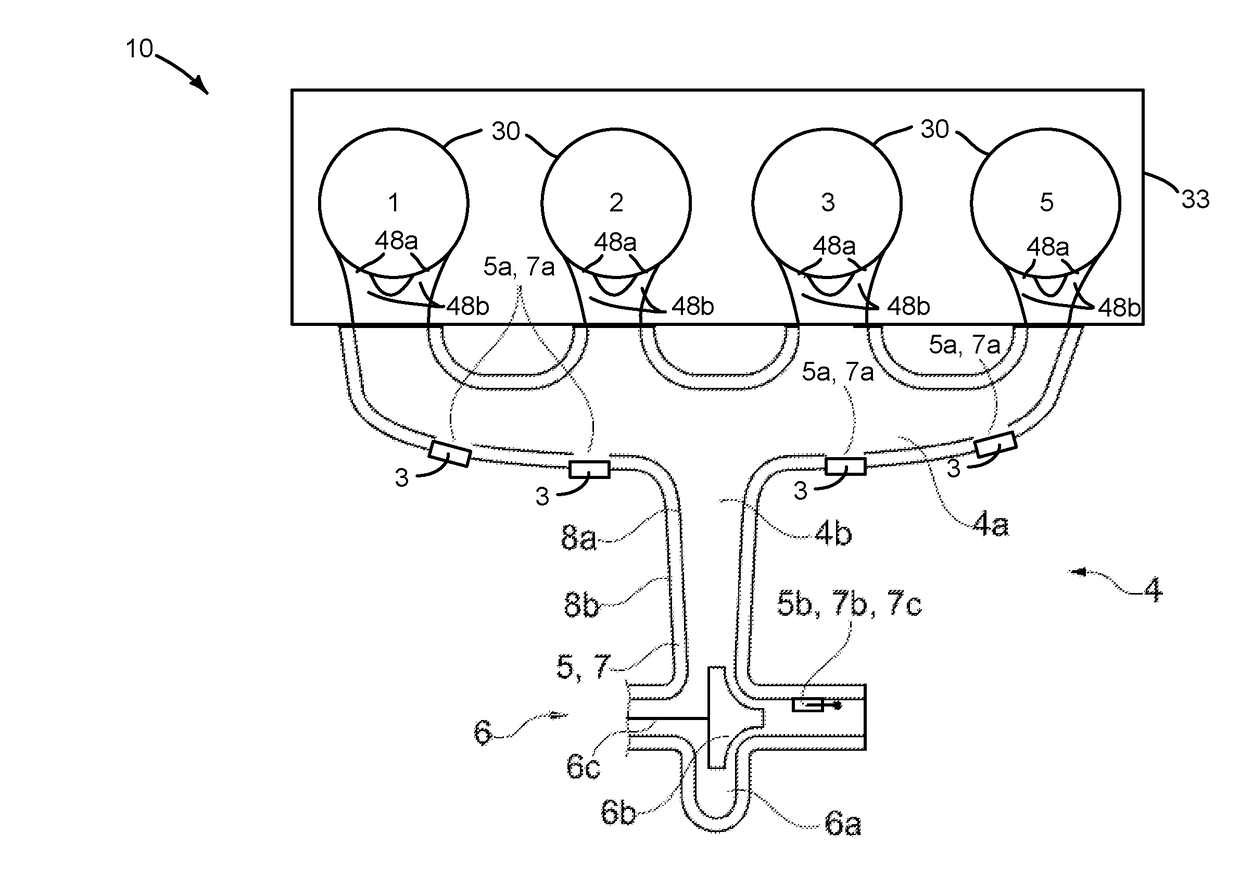
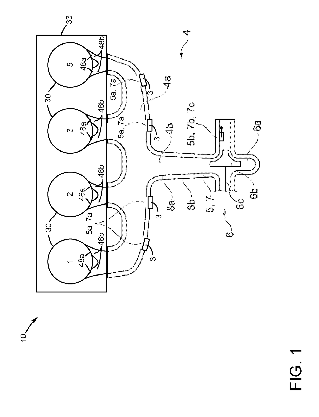
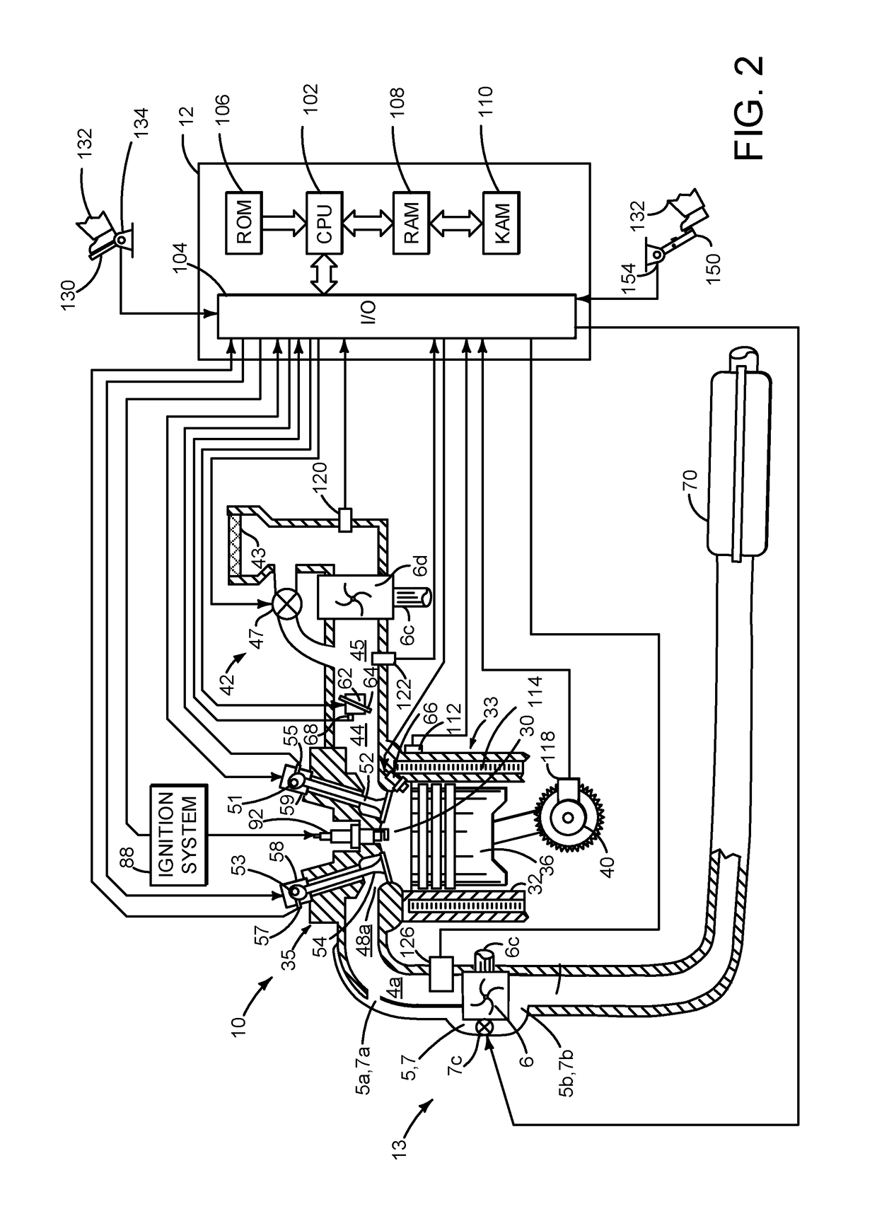
[0036]The present description is related to improving operation of a turbocharged engine. The engine may be configured as shown in FIG. 1. The engine may be included in a system as shown in FIG. 2. The engine and engine system may operate as is shown in FIG. 3. The system may be operated via a controller according to the method of FIG. 4.

[0037]Along with the already stated object, it is a further sub-object of the present invention to specify a method for operating a supercharged internal combustion engine of the stated type. The exhaust-gas discharge system of the internal combustion engine according to the invention is equipped with at least one cavity, which can be utilized, that is to say used, selectively and as required as thermal insulation or as a bypass or bypass line of the wastegate turbine. To be able to serve as a bypass for the wastegate turbine, the at least one cavity is at least connectable, that is to say is connectable for a limited time as required or is permanen...


PUM


Abstract

Systems and methods for operating an engine that includes a cavity in an exhaust manifold of a turbocharged engine are described. The systems and methods may improve engine efficiency and provide a way of controlling temperatures of engine exhaust components. The cavity may be located between an exterior wall of the exhaust manifold and an interior wall of the exhaust manifold.

Description

CROSS REFERENCE TO RELATED APPLICATION[0001]The present application claims priority to German Patent Application No. 102016213386.1, filed Jul. 21, 2016. The entire contents of the above-referenced application are hereby incorporated by reference in its entirety for all purposes.FIELD[0002]The present description relates to methods and a system for operating a turbocharged engine. The methods and systems may be particularly useful for reducing engine cold starting emissions and reducing engine exhaust backpressure at higher engine loads.BACKGROUND AND SUMMARY[0003]An internal combustion engine of the type mentioned in the introduction is used for example as a motor vehicle drive unit. Within the context of the present invention, the expression “internal combustion engine” encompasses Otto-cycle engines, diesel engines and also hybrid internal combustion engines, which utilize a hybrid combustion process, and also hybrid drives which comprise not only the internal combustion engine b...

Claims


Application Information

Patent Timeline
Patent Type & Authority Applications(United States)
IPC IPC(8): F02B37/18F01D17/10
CPCF02B37/183F05D2260/231F05D2220/40F01D17/105Y02T10/12
Inventor KINDL, HELMUT MATTHIASFRIEDERICHS, HANNOKEMMERLING, JOERGSMILJANOVSKI, VANCOKUSKE, ANDREASSOMMERHOFF, FRANZ ARND
Owner FORD GLOBAL TECH LLC
Why Eureka
Try Eureka