
Internal combustion engine and method for operating an internal combustion engine

Active Publication Date: 2015-03-19
FORD GLOBAL TECH LLC
View PDF12 Cites 3 Cited by
  • Summary
  • Abstract
  • Description
  • Claims
  • Application Information

AI Technical Summary

Benefits of technology

The patent text introduces a new technology and its general purpose. The details of the technology are described in the accompanying text. The technical effects of the technology are currently unknown and may not solve any specific problem in the text. The text also mentions that the claimed technology is not limited to any specific solution.

Problems solved by technology

However, generating turbulence in the intake system increases losses in the intake system, decreasing engine efficiency and subverting the aforementioned objective of increased efficiency.
Engine packaging constraints may also affect the generation of a flow pattern for improved mixing the intake air and fuel in the cylinder.

Method used


Image

  • Internal combustion engine and method for operating an internal combustion engine
  • Internal combustion engine and method for operating an internal combustion engine
  • Internal combustion engine and method for operating an internal combustion engine

Examples


Embodiment Construction

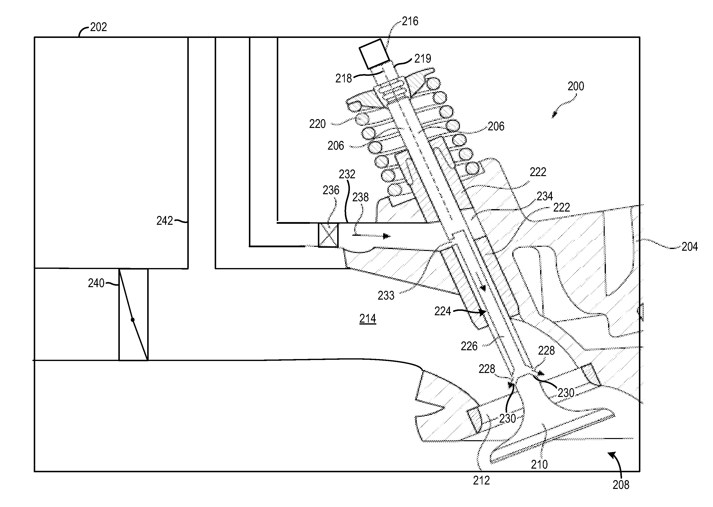
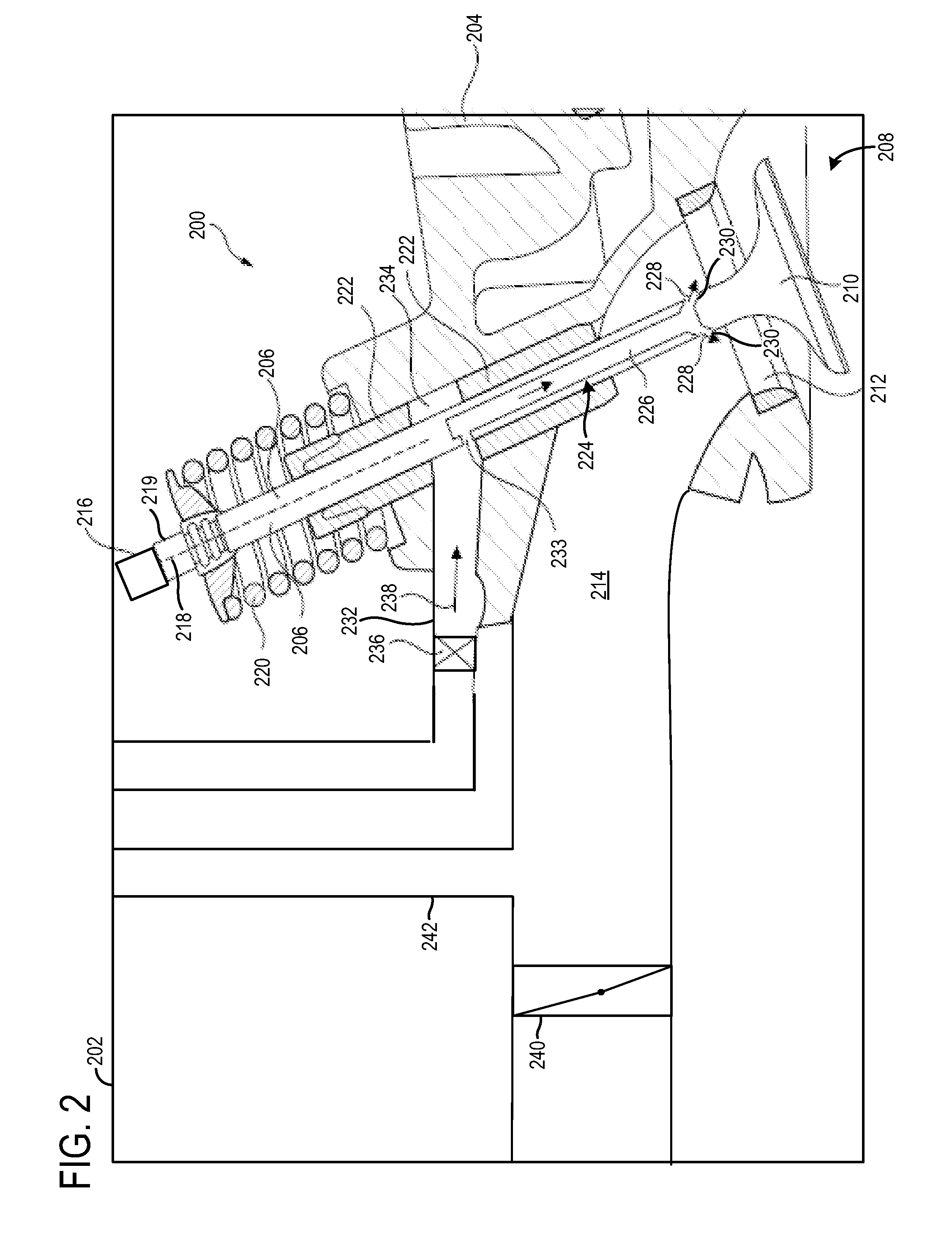
[0012]An internal combustion engine is described herein. The internal combustion engine may include at least one cylinder head and at least one cylinder which has at least one inlet opening fluidly connected to an intake system configured to generate charge air, and a valve assembly comprising a lifting valve for each inlet opening and comprising a valve actuating device for actuating the at least one lifting valve, which valve actuating device comprises at least one overhead camshaft with at least one cam, where each lifting valve has a valve stem, on whose end facing toward the cylinder there is arranged a valve head corresponding to the inlet opening and whose other end faces toward the valve actuating device and which is mounted so as to be displaceable in translational fashion in a bushing-like valve stem guide such that the valve, when actuated and during rotation of the camshaft, performs an oscillating lifting movement in the direction of its longitudinal axis between a valv...


PUM


Abstract

An intake system for an internal combustion engine is provided. The intake system may include an intake manifold fluidly connected to a cylinder, an intake valve coupled to the cylinder having an air supply duct longitudinally extending through a portion of a valve stem and having an outlet opening into the intake manifold and an inlet fluidly connected to a supply line fluidly connected to an intake passage downstream of a compressor and upstream of a throttle, and a shut-off valve positioned in the supply line configured to adjust the flow of gas through the supply line.

Description

CROSS REFERENCE TO RELATED APPLICATIONS[0001]The present application claims priority to German Patent Application No. 102013218773.4, filed Sep. 19, 2013, the entire contents of which are hereby incorporated by reference for all purposes.FIELD[0002]The present disclosure relates to a system and method for routing gases through a passage in a valve stem.BACKGROUND AND SUMMARY[0003]Internal combustion engine utilize intake systems to provide intake air to cylinders in the engine. Improved mixing of the intake air with fuel in the cylinder may be desirable to enable an increase in engine efficiency and decreased engine emissions. Specifically, turbulent flow of the intake air may be generated to improve mixing in the cylinders in the engine. However, generating turbulence in the intake system increases losses in the intake system, decreasing engine efficiency and subverting the aforementioned objective of increased efficiency. Engine packaging constraints may also affect the generation...

Claims


Application Information

Patent Timeline
IPC IPC(8): F02B31/04F01L3/20F02M35/10F01L3/06
CPCF02B31/04F01L3/06F01L3/20F02B2031/003F02M35/10209F02M35/10288F02M35/10124F01L3/12F01L3/16F02M35/10222F02B31/00F02M23/006F02M35/10072F02M26/05F02M26/06Y02T10/12F02B31/08
Inventor PUETZER, JEAN-PHILIPPE
Owner FORD GLOBAL TECH LLC
Learn More