
Method for increasing vacuum production for a vehicle

a technology for vacuum production and vehicles, applied in the direction of electric control, combustion air/fuel air treatment, instruments, etc., can solve the problems of insignificant, higher vehicle cost for such systems, and methods that require hardware, so as to reduce engine emissions, reduce engine pumping losses, and save fuel

Active Publication Date: 2014-12-11
FORD GLOBAL TECH LLC
View PDF5 Cites 4 Cited by
  • Summary
  • Abstract
  • Description
  • Claims
  • Application Information

AI Technical Summary

Benefits of technology

The patent describes a method for operating a vehicle powertrain that reduces the amount of engine torque provided to the wheels, in response to a request for increased vacuum. By doing so, the engine can operate at a higher intake manifold pressure, reducing engine pumping losses and increasing opportunities for vacuum production. This approach does not require additional hardware and is cost-effective. The method also improves the amount of vacuum available for the vehicle and reduces the amount of time required for the engine to produce a desired amount of vacuum. Overall, the technical effect of this patent is to provide an improved vacuum system for vehicles without adding significant cost or affecting the driver's experience.

Problems solved by technology

However, many of these systems and methods require hardware that is additional to more conventional engines.
Consequently, vehicle cost may be higher for such systems.
Further, the approach may not be noticeable to a driver.
In addition, the approach may reduce an amount of time that it takes an engine to produce a desired amount of vacuum.

Method used


Image

  • Method for increasing vacuum production for a vehicle
  • Method for increasing vacuum production for a vehicle
  • Method for increasing vacuum production for a vehicle

Examples


Embodiment Construction

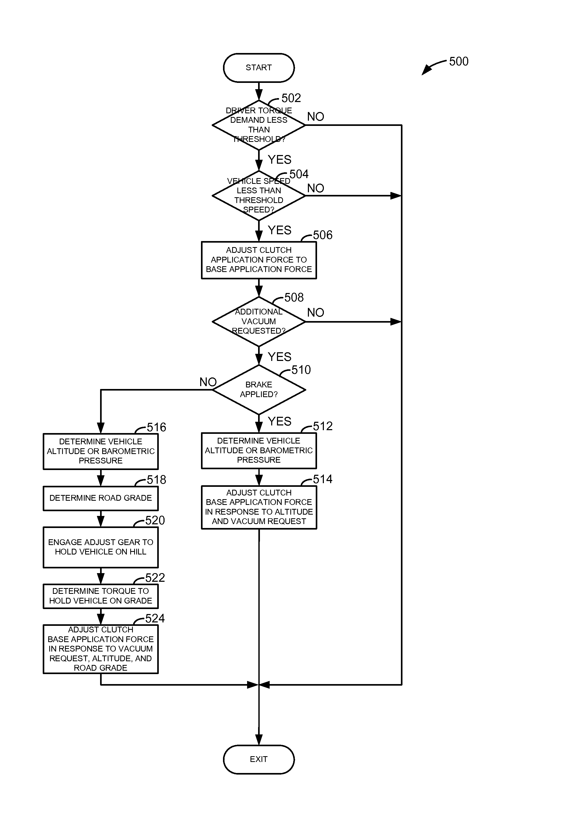
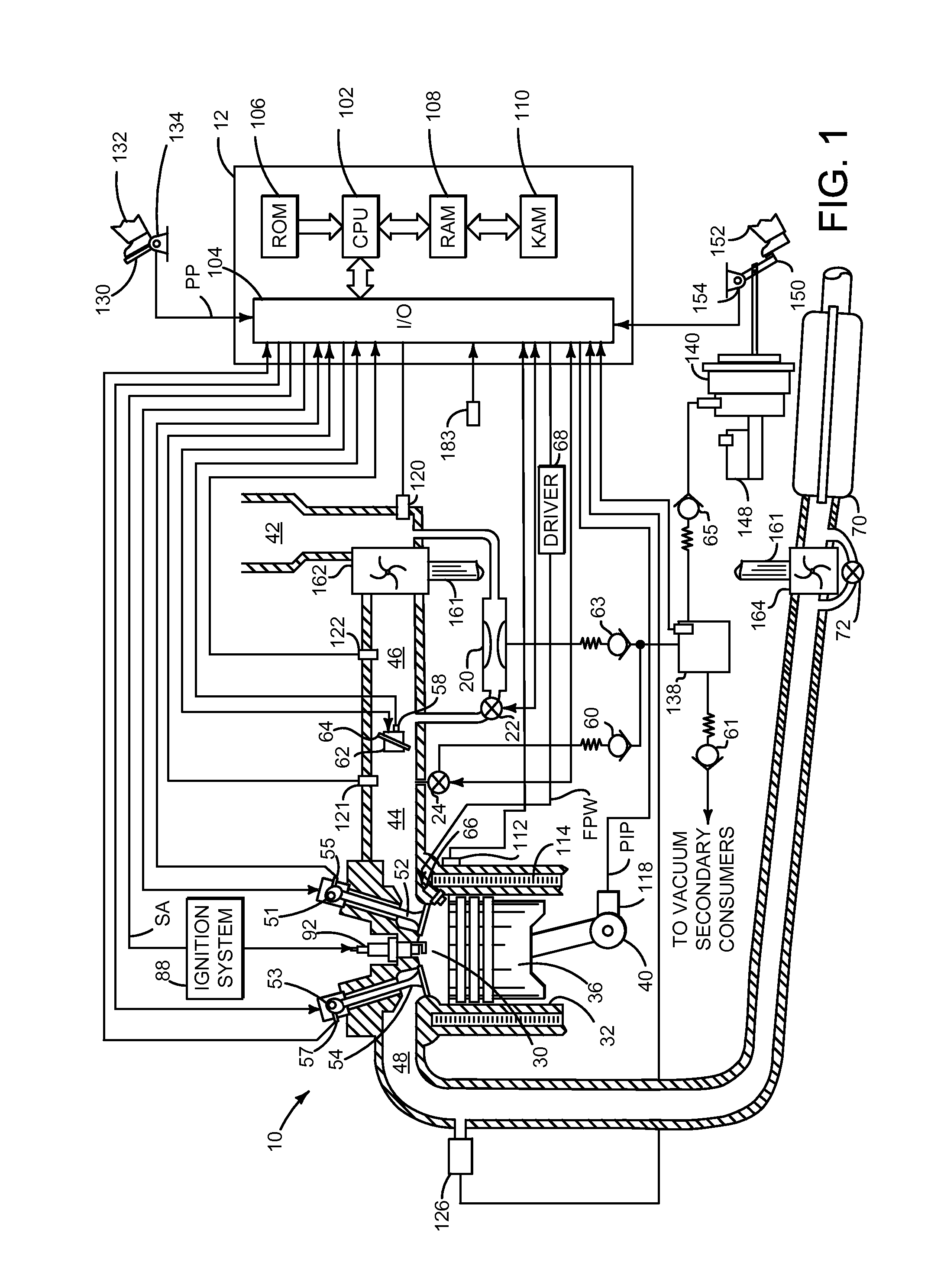
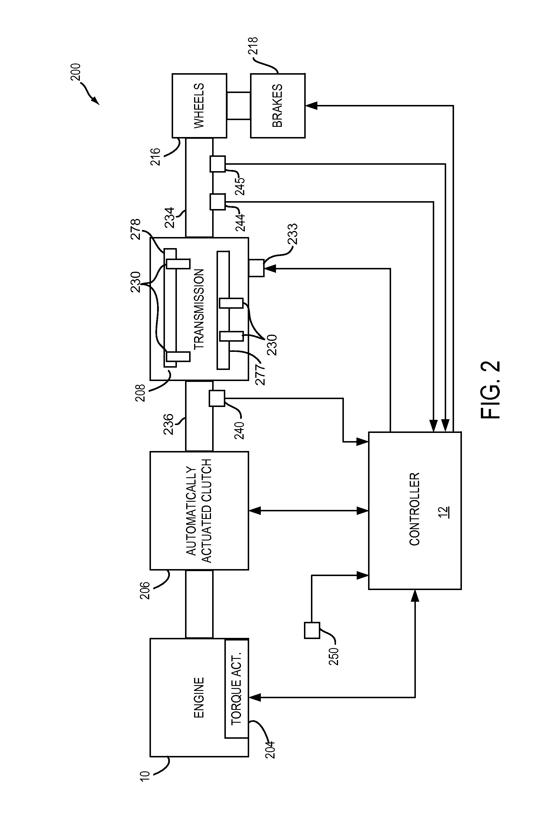
[0014]The present description is related to providing vacuum for vacuum consumers of a vehicle. In one non-limiting example, slip of a transmission input clutch is increased in response to a request for increased vacuum. Engine load may be reduced by increasing transmission clutch slip so that the engine may provide additional vacuum. In one example, the engine may be as illustrated in FIG. 1. Further, the engine may be part of a vehicle powertrain as illustrated in FIG. 2. FIG. 3 shows an example transmission input clutch for an Automatically Shifted Manual (ASM) transmission. In one example, the transmission input clutch may be electrically actuated. However, in other examples, the transmission input clutch or clutches may be hydraulically actuated. FIG. 4 shows an example operating sequence when the method of FIG. 5 is executed via a controller as shown in FIGS. 1 and 2.

[0015]Referring to FIG. 1, internal combustion engine 10, comprising a plurality of cylinders, one cylinder of ...


PUM


Abstract

Methods and systems for providing vacuum to a vehicle are described. In one example, a method adjusts an application force of a transmission clutch in response to a request for additional vacuum.

Description

FIELD[0001]The present description relates to methods and systems for operating an engine that produces vacuum for a vehicle. The methods and systems may be particularly useful for engines that are boosted and that operate at high altitudes.BACKGROUND AND SUMMARY[0002]Vehicle engines may be downsized to conserve fuel and reduce engine emissions. Smaller engines may operate more frequently at higher intake manifold pressures as compared to larger engines in the same vehicle. Engine pumping losses may be reduced by operating an engine with higher intake manifold pressures, but the opportunities to provide engine vacuum to the vehicle vacuum system may be reduced. Some attempts to increase vacuum production have included ejectors, ways of advantageously controlling engine throttle position, and various other control strategies. However, many of these systems and methods require hardware that is additional to more conventional engines. Consequently, vehicle cost may be higher for such s...

Claims


Application Information

Patent Timeline
Patent Type & Authority Applications(United States)
IPC IPC(8): B60W10/06B60W10/02
CPCB60W10/06B60W10/02B60W30/188B60W30/18063F02M35/10229Y10S477/901Y10T477/6403F02D41/30B60W2710/021B60W2710/02B60W2710/065B60W2710/0666B60W2520/30B60W2510/1005B60W2510/18B60W2552/15
Inventor CUNNINGHAM, RALPH WAYNEPURSIFULL, ROSS DYKSTRA
Owner FORD GLOBAL TECH LLC
Learn More