Efficiency improvements for flow control body and system shocks

Inactive Publication Date: 2017-05-18
IRELAND PETER +1
View PDF4 Cites 41 Cited by
  • Summary
  • Abstract
  • Description
  • Claims
  • Application Information

AI Technical Summary

Benefits of technology

[0090]Note that it is not typically possible to eradicate normal or even oblique shocks directly, since these are caused by fluid-flow interactions caused by flow controlling surfaces that decelerate a fluid-flow (even to below the local sonic speed) and hence cause an entropy or energy loss. What is possible is that this new art embodiment can be configured by; design, experimenta

Problems solved by technology

This again proves on a real flying aircraft that the wing L/D ratio is compromised due to a LE Slat type of spanwise AFS flow discontinuity and resulting flow disturbance.
This is particularly tr

Method used


Image

  • Efficiency improvements for flow control body and system shocks
  • Efficiency improvements for flow control body and system shocks
  • Efficiency improvements for flow control body and system shocks

Examples


Embodiment Construction

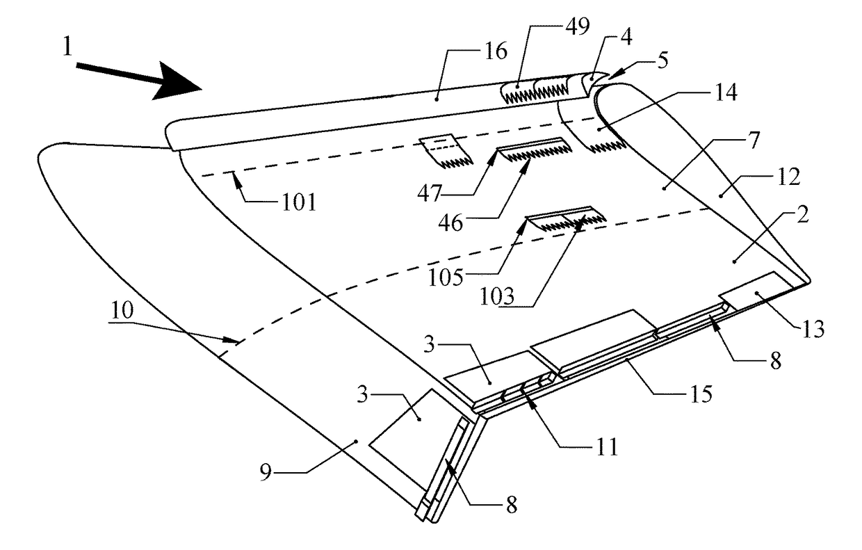
[0107]FIG. 1 shows the arrangement of a common example of a wing 2 with both a downward deflecting TE flap 3 before the TE 15, and a LE Slat 4 in the un-retracted low-speed position at the wing LE 16. The relative incoming fluid-flow or upstream freestream 1 is shown by an arrow and this allows the AoA to be defined by the relative angular deflection of the wing chord line (or the flow control surface extents) from this freestream velocity vector. Slat slot 5 open in the low-speed extended configuration accelerates additional fluid-flow over the wing top or suction face 6. A wing pressure face 7 TE array of eLET body 8 are configured as the required coverage from near the wing tip 12 to wing root, and possible Yehudi root rear chord extension 9. Wing TE array of eLET body 8 are applied in sections to ensure fault-tolerance if any section becomes detached in flight. This is critically important because this TE array of eLET body 8 addition changes the local wing CL, as well as CD, wh...


PUM


Abstract

Methods and related apparatus embodiments are disclosed that allow novel Conformal Vortex Generator and/or Elastomeric Vortex Generator art to improve energy efficiency and control capabilities at many surface points of a body or object moving at speed in aero/hydrodynamic Newtonian fluids, by reducing; shock energy losses, surface flow turbulence, and/or momentum layer thicknesses.

Description

CROSS-REFERENCE TO RELATED APPLICATIONS[0001]This application is a continuation-in-part of International application PCT / IB 13 / 50676 filed 25 Jan. 2013, which is a continuation-in-part of US National stage application US2011 / 0006165A1 filed Jul. 8, 2010, which is the non-provisional application derived from provisional U.S. application 61 / 224,481 filed Jul. 10, 2009, also filed as International application PCT / IB2010 / 001885 on Jul. 9, 2010. This application is filed prior to publishing of parent PCT / IB 13 / 50676, and incorporates by reference all earlier applications, and hence is limited by parent applications in a terminal disclaimer condition as required.BACKGROUND OF THE INVENTION[0002]Field of the Invention[0003]This invention is in the field of improving; shock losses, and / or flow losses from normal or oblique Shock Boundary Layer Interaction (SBLI) or Shock Wave Boundary Layer Interaction (SWBLI), in addition to control of flow separation and turbulent flow losses, on the flui...

Claims


Application Information

Patent Timeline
IPC IPC(8): B64C23/06B64C21/10F04D29/32F01D9/02F23R3/00F04D27/00F01D5/14B64F5/60F04D29/54
CPCB64C23/06B64F5/60B64C21/10F04D29/324F04D29/542B64C2230/26F23R3/002F04D27/009F01D5/147F01D9/02F04D29/545F04D29/681F05D2250/182F05D2250/183F01D5/145F05D2240/127F15D1/12F15D1/003Y02T50/10Y02T50/60
Inventor IRELAND, PETERIRELAND, ANTHONY
Owner IRELAND PETER
Why Eureka
Try Eureka