Roadway for decelerating and/or accelerating a vehicle including an aircraft

a technology for accelerating and decelerating vehicles, which is applied in the direction of roads, traffic signals, transportation and packaging, etc., can solve the problems of easy sideways and slippage of tires, vehicle may easily be rendered minimally controllable, and vehicle experience a fairly bumpy ride, so as to reduce the required length of runways, minimize the braking system, and reduce the stress on the structure of the airplane

Inactive Publication Date: 2005-11-29
OMNITEK PARTNERS LLC
View PDF24 Cites 47 Cited by
  • Summary
  • Abstract
  • Description
  • Claims
  • Application Information

AI Technical Summary

Benefits of technology

[0023]9. The entire or a major segment of the runway may be constructed as a RAR unit, thereby allowing planes to use them to bring them to a stop with minimal or less use of their brakes, thereby minimizing braking system, tire, and runway wear.
[0024]Another objective of the present invention is to provide the means to reduce the required length of runways for landing airplanes, while reducing stress on the structure of the airplane during hard braking, reducing tire wear, reducing brake wear, and making the airplane more controllable during its deceleration. Deceleration by braking is the result of the work done by the friction force between the tire and the road surface. This friction force tends to tip over the vehicle since it acts at a point away (below) the center of mass of the vehicle. In this regard, an advantage of the RAR runways is that it can decelerate vehicles without the tendency of tipping them over.
[0025]Another objective of the present invention is to provide the means to reduce the required length of runways for airplane takeoff, while reducing the stress on the structure of the plane and saving fuel.
[0026]Another objective of the present invention is to provide RAR segments that partially disabled airplanes may use for landing with greatly increased probability of coming to stop safely rather than, e.g., sliding uncontrollably to a stop over great distances, which could mean leaving the runway and striking some obstacles or falling into a ditch or water. In addition, since the runway surface is readily accessible from under the RAR surface panels, provisions can be made to introduce highly sticky and / or fire retardant or fire distinguishing substances such as fluid or foam to the surface of the runway or spray the same some distance above the surface over the incoming vehicle to significantly reduce the probability of fire and / or introduce fire inhibiting gases so that the spilled fuel could not be ignited and / or prevent the fire from spreading.

Problems solved by technology

As the vehicle travels along the sand-filled road, the vehicle usually experiences a fairly bumpy ride, since the sand cannot be made and maintained perfectly flat and perfectly homogeneous or protected from contaminants carried by the wind and rain and also by an uneven absorption of moisture.
Another major disadvantage of the sand is that due to the relatively small friction that it provides between the tire and the roadway, the tires can easily skid sideways and slip, particularly if the driver attempts to use the brakes, and the vehicle may easily be rendered minimally controllable while slowing down.
As a result, accidents, such as overturning and jackknifing, can occur while the vehicle is being brought to rest.
In addition, a depth of sand that is most appropriate for a certain vehicle weight, number of tires, and / or tire size may not be appropriate for other vehicles having a significantly different weight, number of tires, and / or tire size.
For example, a road with a depth of sand that is appropriate for a heavy truck will decelerate a light vehicle too fast and can therefore result in injury to the passengers due to the rapid deceleration and / or most likely due to the vehicle loss of control.
Such conditions cannot obviously be met for roads that are constructed for general use and are subject to various environmental conditions.
Such sand-filled roads are not, however, suitable for fast moving vehicles such as airplanes.
For the case of airplanes, other issues may also arise.
For example, the load on each tire is usually much larger than road vehicles; the relative distance between the tires may be smaller than those of road vehicles, thereby rendering them more uncontrollable; the center of mass of the plane may be higher than that of road vehicles, thereby making them more prone to tipping over; etc.
In addition, and particularly for fast moving planes, the load applied to the tires keep varying due to the suspensions and the lift action, and therefore may cause a ripple to be formed on the surface of the sand-filled road, thereby making the ride even more bumpy and uncontrollable.
In short, sand-filled roads are not appropriate and practical for fast moving vehicles in general and for airplanes in particular.
However, such runway segments leave some of the major aforementioned problems unsolved and they even create some new problems and hazards.
For example, the problem of lack of control is only partially solved by reducing the skidding potential caused by the sand.
However, the collapsed concrete tends to constrain the tire to travel, more or less, in the generated “groove,” making it difficult for the plane to maneuver (turn) sideways due to the resistance that the uncrushed “concrete wall” provides against the tire as it attempts to turn sideways.
In addition, the concrete material cannot be formed such that it is sufficiently homogeneous to prevent bumpy rides.
In addition, the collapsible concrete runway can only be optimally formulated and constructed for a certain airplane with a certain total weight and certain initial velocity as it reaches the collapsible segment of the runway.
Furthermore, once the collapsible segment of the runway is used by a “runaway” plane during landing or takeoff, the damaged segment has to be repaired before the runway can be opened to traffic.
Otherwise, the damaged segment would pose a hazardous condition for the next runaway plane or even for a plane that could have stopped if a regular runway segment was present in place of the collapsible segment.
In addition, while the repair crew is repairing the damage, any takeoff or landing would pose a hazardous condition for the repair crew and the plane.
In short, the operation of the airport must be significantly curtailed for a significant length of time and if the airport has only one runway, the entire operation of the airport has to be suspended until the damaged sections of the collapsible runway has been repaired.
In short, such collapsible runway segments have major technical difficulties for safe operation and even those technical problems are one day solved, they are still effectively impractical due to the required relatively long periods of closure after each use and the related economical costs involved.

Method used


Image

  • Roadway for decelerating and/or accelerating a vehicle including an aircraft
  • Roadway for decelerating and/or accelerating a vehicle including an aircraft
  • Roadway for decelerating and/or accelerating a vehicle including an aircraft

Examples


Embodiment Construction

[0048]Although this invention is applicable to numerous and various types of roadways and surfaces, it has been found particularly useful in the environment of runways for aircraft. Therefore, without limiting the applicability of the invention to runways for aircraft, the invention will be described in such environment. Those skilled in the art will appreciate that the RAR of the present invention can be used on roadways for automobiles and trucks and for other wheeled vehicles. The RAR of the present invention can also be adapted for use with trains where the panels described below are proximate the rails upon which the trains travel.

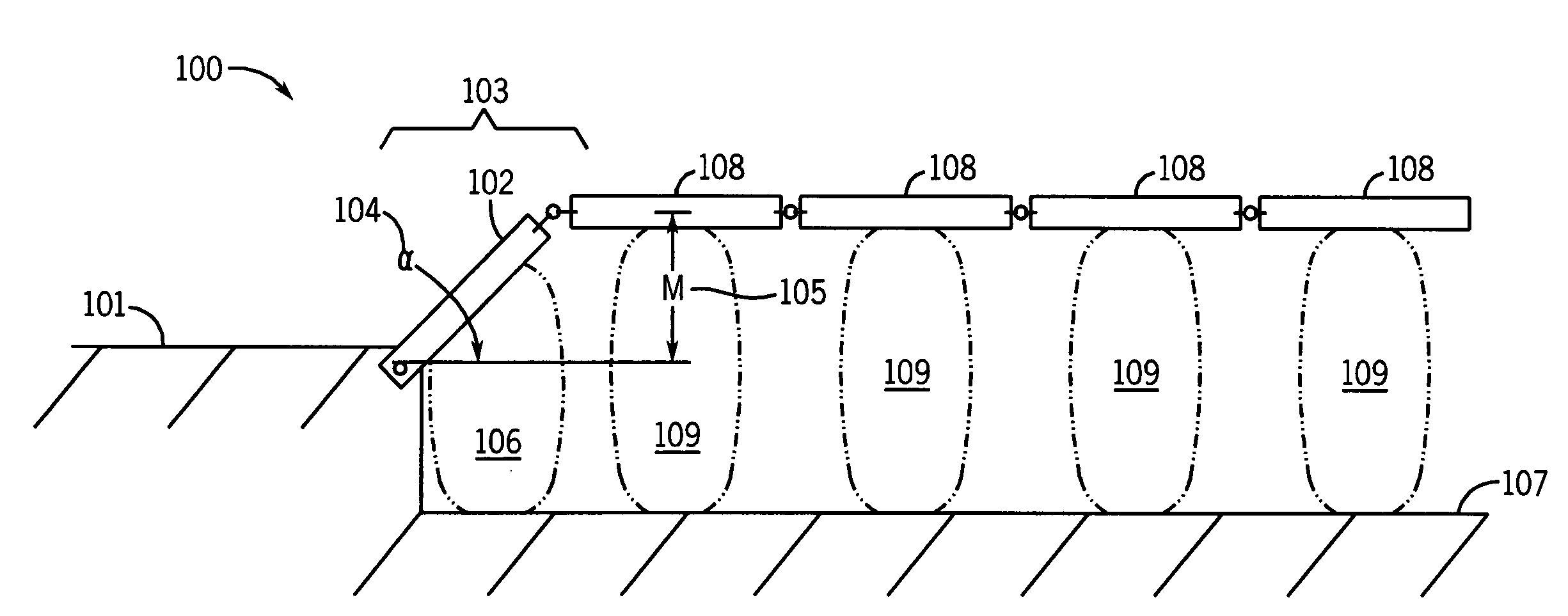
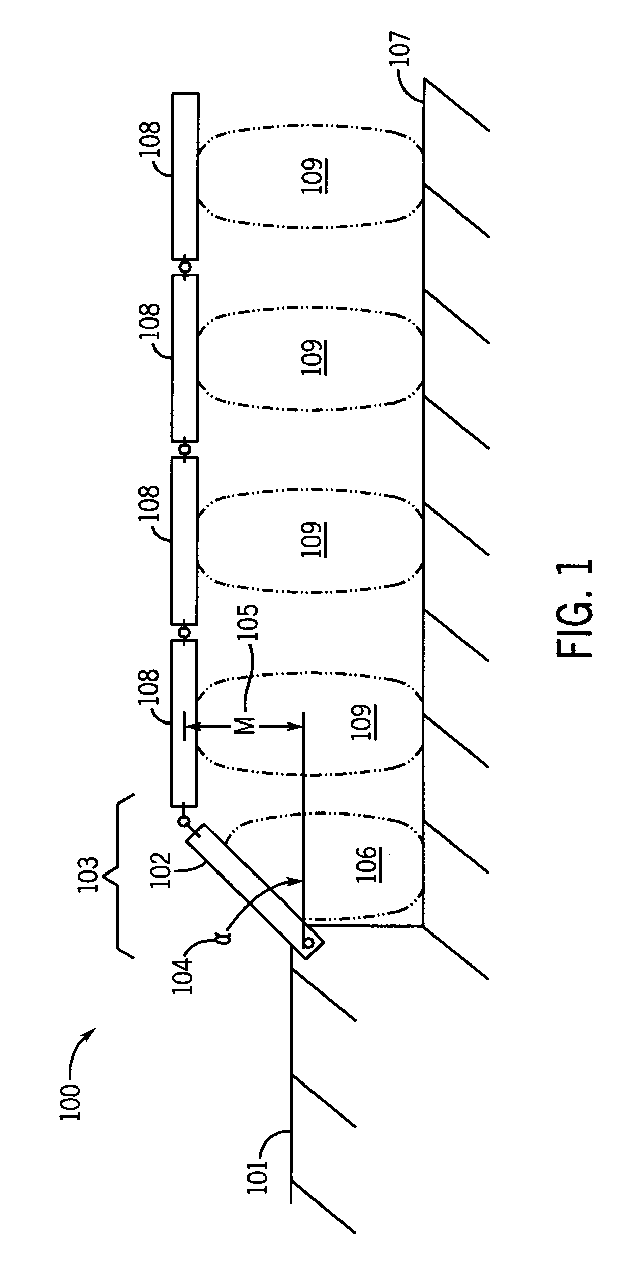
[0049]A schematic of the side view of a preferred RAR illustrating its basic principles of operation is shown in FIG. 1. In this illustration, the RAR 100 segment is shown positioned at the end of a typical (fixed) runway 101. At the end of the fixed runway 101, one or more transition runway panels 102 are to be installed in a transition segment 103 o...


PUM


Abstract

A roadway upon which a vehicle travels is provided in which the vehicle is decelerated. The roadway includes: a movable surface extending in a direction of the vehicle's travel; and a potential energy storage mechanism operatively connected to the movable surface for converting a kinetic energy of the vehicle into potential energy upon movement of the movable surface thereby slowing the vehicle. Also provided is a roadway upon which a wheeled vehicle travels in which the vehicle is accelerated. The roadway includes: a movable surface extending in a direction of the vehicle's travel; and a potential energy transfer mechanism operatively connected to the movable surface for transferring a stored potential energy associated with the movable surface into kinetic energy upon movement of the movable surface thereby propelling the vehicle.

Description

BACKGROUND OF THE INVENTION[0001]1. Field of the Invention[0002]The present invention relates generally to moving objects and devices for use therewith; and more particularly, to methods and devices for accelerating and decelerating moving vehicles.[0003]2. Prior Art[0004]Along many highways, exits are provided for runaway trucks or other types of vehicles. Once a vehicle takes such an exit, it enters a stretch of a road that is filled with relatively fine sand of an appropriate depth. As the runaway vehicle enters the sand-filled portion of the road, it quickly begins to decelerate and slow down and after a relatively short distance it comes to rest. The deceleration of the vehicle is caused primarily by the process of “sinking” the vehicle tires into the sand, and forcing it to continuously climb the height of the sand in front of it, i.e., a height equal to the sinking depth of the tire. The kinetic energy of the vehicle is absorbed primarily by the friction forces generated with...

Claims


Application Information

Patent Timeline
Patent Type & Authority Patents(United States)
IPC IPC(8): B64F1/02E01C9/00E01F13/12
CPCB64F1/02E01C9/007E01F13/123B64F1/025Y02T50/82Y02T50/80
Inventor RASTEGAR, JAHANGIR S.GE, QIAODE JEFFREY
Owner OMNITEK PARTNERS LLC
Why Eureka
Try Eureka