Battery Combined System

Inactive Publication Date: 2015-10-22
HITACHI LTD
View PDF3 Cites 6 Cited by
  • Summary
  • Abstract
  • Description
  • Claims
  • Application Information

AI Technical Summary

Benefits of technology

[0014]According to the present invention, by adjusting an SOC of a power type battery, a frequency at which the SOC reaches an upper limit or a lower limit is reduced, and ther

Problems solved by technology

As a result, a system that increases an unnecessary battery is designed.
Such design increases cost, an

Method used


Image

  • Battery Combined System
  • Battery Combined System
  • Battery Combined System

Examples


first embodiment

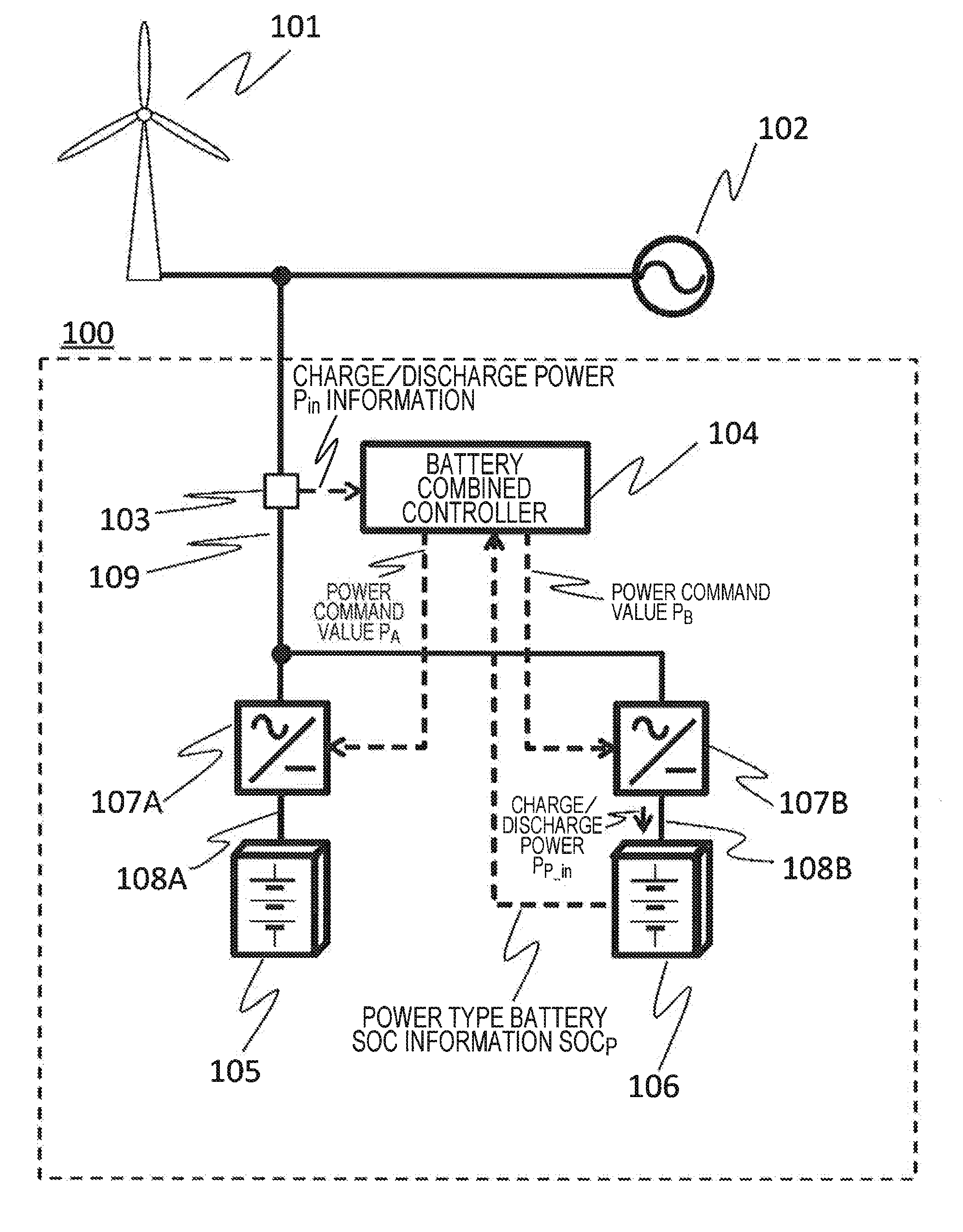
[0026]A battery combined system 100 will be described with reference to FIG. 1.

[0027]The battery combined system 100 includes an inverter 107A and an inverter 107B. A capacity type battery 105 including multiple batteries and a power type battery 106 including multiple batteries are respectively connected on DC line (108A and 108B) sides of each inverter. Also, each of the inverter 107A and the inverter 107B are parallelly connected each other on an AC line 109 side and connected to a power generation device 101 and a power system 102, which are located outside of the battery combined system 100. Also, a power measuring device 103 is provided on the AC line 109.

[0028]The power measuring device 103 has functions to measure charge / discharge power Pin to be input to the battery combined system 100 and to transmit the measurement to a battery combined controller 104. In the charge / discharge power Pin to be input to the battery combined system 100, and charge / discharge powers PE—in and P...

second embodiment

[0061]A second embodiment will be described next.

[0062]An overall configuration of the second embodiment is similar to the overall configuration of the first embodiment illustrated in FIG. 1. The second embodiment differs from the first embodiment in that a first threshold value Tr1 and a second threshold value Tr2 are changed in the case of Pin>PE—max and in the case of PE—min>Pin.

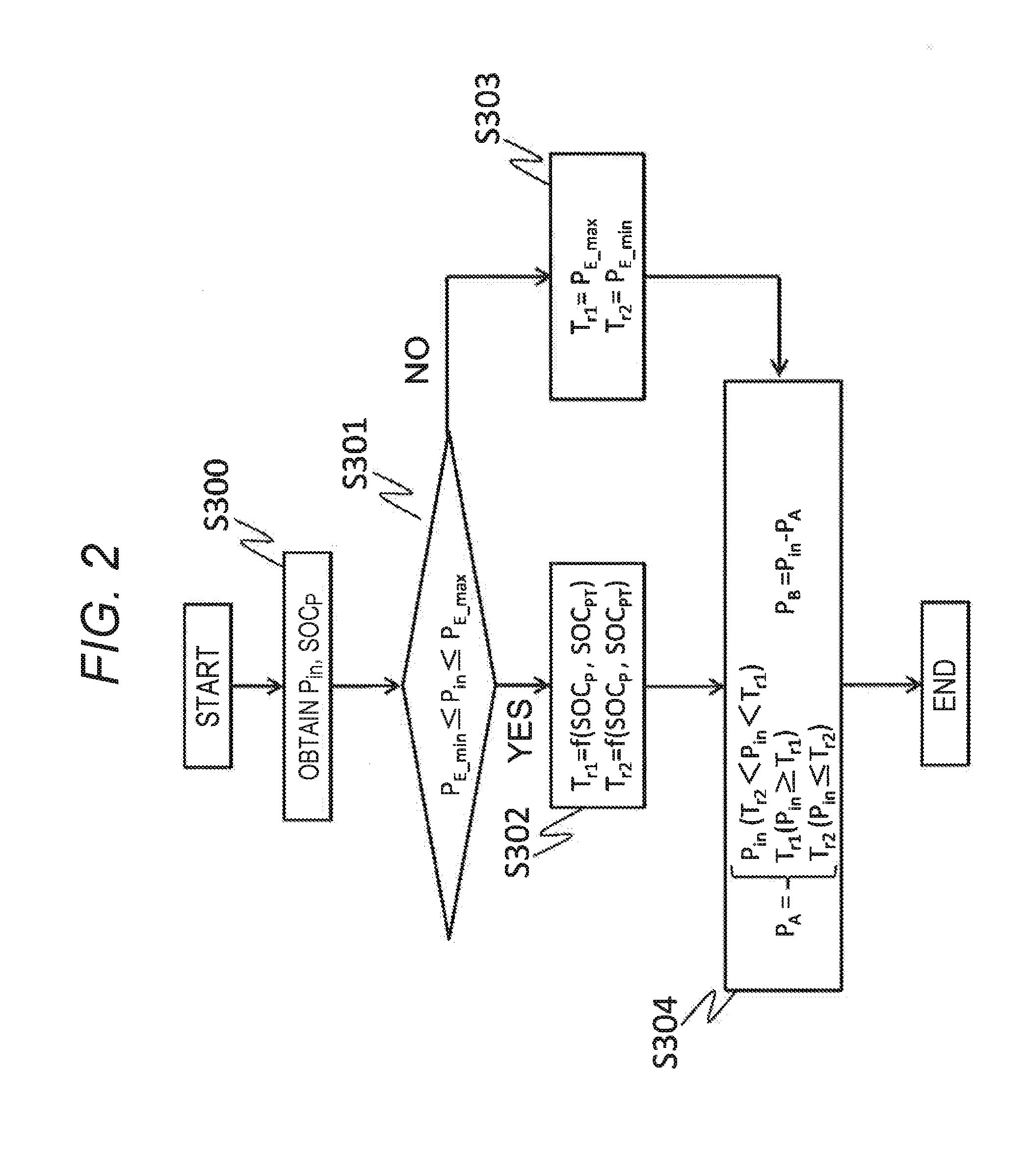
[0063]FIG. 6 is a flowchart illustrating a calculation procedure for inverter power command values PA and PB of a battery combined controller 104 according to the second embodiment. In the second embodiment, in step S313, the first threshold value Tr1 and the second threshold value Tr2 are variable depending on an SOCP of a power type battery 106.

[0064]A calculation example of the first threshold value Tr1 and the second threshold value Tr2 in step S313 is indicated in formulas (5) and (6) by using the SOCP of the power type battery 106, and upper and lower limits SOCPmin and SOCPmax of the SOCP, and a co...

third embodiment

[0067]A third embodiment will be described next.

[0068]An overall configuration of the third embodiment and a flowchart illustrating a calculation procedure for inverter power command values PA and PB are similar to those of the first embodiment illustrated in FIG. 1 and FIG. 2. The third embodiment differs from the first embodiment in that a calculation method for a first threshold value Tr1 and a second threshold value Tr2, which have been determined in step S302, is changed.

[0069]FIG. 9(a) is a correlation diagram in which the correlation, illustrated in FIG. 3(a) according to the first embodiment, between the SOCP of the power type battery 106 and the first threshold value Tr1 and the second threshold value Tr2 is changed. In the third embodiment, when a SOCP of a power type battery 106 is within a range of ±α2 of a target SOCPT, a first threshold value Tr1 and a second threshold value Tr2 are respectively PE—max and PE—min.

[0070]As an example of a method for calculating the firs...


PUM


Abstract

Provided is a battery combined system in which a system operation rate is improved by reducing, in comparison with a conventional method, a frequency at which an SOC of a power type battery reaches an upper limit or a lower limit. The battery combined system according to the present invention is a battery combined system in which a capacity type battery and a power type battery having a higher output value with respect to a capacity (output/capacity) than that of the capacity type battery are connected in parallel. The battery combined system changes a threshold value to distribute charge/discharge power to the power type battery or the capacity type battery in the case where the charge/discharge power is equal to or less than maximum charge power and equal to or larger than maximum discharge power of the capacity type power.

Description

TECHNICAL FIELD[0001]The present invention relates to a battery combined system in which multiple batteries having different characteristics are combined.BACKGROUND ART[0002]Currently, power to be supplied to the society is generated by burning fossil fuels, such as oil and coal, to generate high temperature / high pressure steam, and thereby rotating a steam turbine. However, recently, a power generation system using natural energy (such as solar power generation and wind power generation) is increasing in terms of environmental considerations.[0003]There is a system for smoothing power to be output to a power system by providing a large scale battery system connected to multiple storage batteries in multiple series parallel with respect to the power generation system using natural energy. However, since a charge / discharge power pattern of a battery of this battery system varies depending on installation environment (a wind speed and a solar radiation amount), necessary output (W) an...

Claims


Application Information

Patent Timeline
IPC IPC(8): H02J7/00
CPCH02J7/0021H02J3/32H02J2300/28H02J3/381Y02E10/76Y02E70/30
Inventor TAKAHASHI, CHIAKITAKEDA, KENJIINOUE, TAKESHI
Owner HITACHI LTD
Why Eureka
Try Eureka