Method and system for fuel system control

a fuel system and control system technology, applied in the field of fuel systems, can solve the problems of low pumped voltage response of the closed loop pressure control system to the output reading of the pressure sensor, the deformation of the pressure sensor in the lift pump, and the failure of the in-range pressure sensor, so as to reduce the potential for fuel vapor generation at the inlet of the high-pressure pump, reduce the energy consumption of the fuel system, and improve the operation of the fuel system.

Active Publication Date: 2016-05-26
FORD GLOBAL TECH LLC
View PDF13 Cites 14 Cited by
  • Summary
  • Abstract
  • Description
  • Claims
  • Application Information

AI Technical Summary

Benefits of technology

[0005]In one example, a fuel system includes a lift pump for delivering fuel from the fuel tank to a high pressure fuel pump. The high pressure fuel pump may be coupled to a fuel rail delivering fuel to cylinder direct fuel injectors. The lift pump may be operated predominantly in a continuous power mode. Therein, based on a fuel pressure and fuel flow rate required to meet the fueling demand, a voltage (or speed, current, duty cycle, torque, or power) applied to the lift pump may be determined. For example, as the commanded fuel pressure increases, the command and pump voltage may also be increased, and likewise, as the commanded fuel pressure decreases, the commanded pump voltage may also decrease. However, a minimum clip may be applied to the pump voltage to enforce a minimum lift pump pressure. The minimum pressure, and corresponding minimum pump voltage, may be determined based on fuel vapor pressure and fuel flow rate. In other words, if the commanded pump voltage is below the minimum pump voltage, a controller may override the commanded pump voltage and apply the minimum pump voltage instead. Since the lift pump pressure is controlled in a closed loop manner with a PID controller, during the clipping, the integral term may be transiently frozen or reset (e.g., to zero). The lift pump may additionally be operated in a pulsed mode wherein lift pump voltage is adjusted based on lift pump pressure estimated by a lift pump pressure sensor. However, by applying the minimum pump voltage during conditions when the commanded pump voltage is lower, the potential for fuel vapor generation at the inlet of the high pressure pump is reduced. This, in turn, reduces the need for frequent lift pump pulsing.
[0006]In this way, a low voltage clip is applied to a lift pump command to ensure that the fuel system always makes a minimum pressure. As such this ensures a basic function of the pump system. By enforcing a minimum voltage on the lift pump that is a function of the commanded lift pump pressure, the closed loop controller may account for pump degradation. In addition, fuel system operation is improved even during conditions when a lift pump pressure sensor output is unreliable. Overall, engine stalls due to ingestion of vapor pressure at a high pressure fuel pump inlet is reduced. Further, by reducing the need for frequent lift pump pulsing, fuel system energy consumption is reduced.

Problems solved by technology

However, the inventors herein have identified potential issues with such systems.
Lift pump pressure sensors may degrade.
In particular, they may fail in-range while reading a higher pressure than actually is present.
As a result, the closed loop pressure control system may drop that pumped voltage in response to the pressure sensor output reading falsely high.
The presence of fuel vapors at the pump inlet of the high pressure fuel pump can result in a precipitous drop in fuel rail pressure, causing the engine to stall.

Method used


Image

  • Method and system for fuel system control
  • Method and system for fuel system control
  • Method and system for fuel system control

Examples


Embodiment Construction

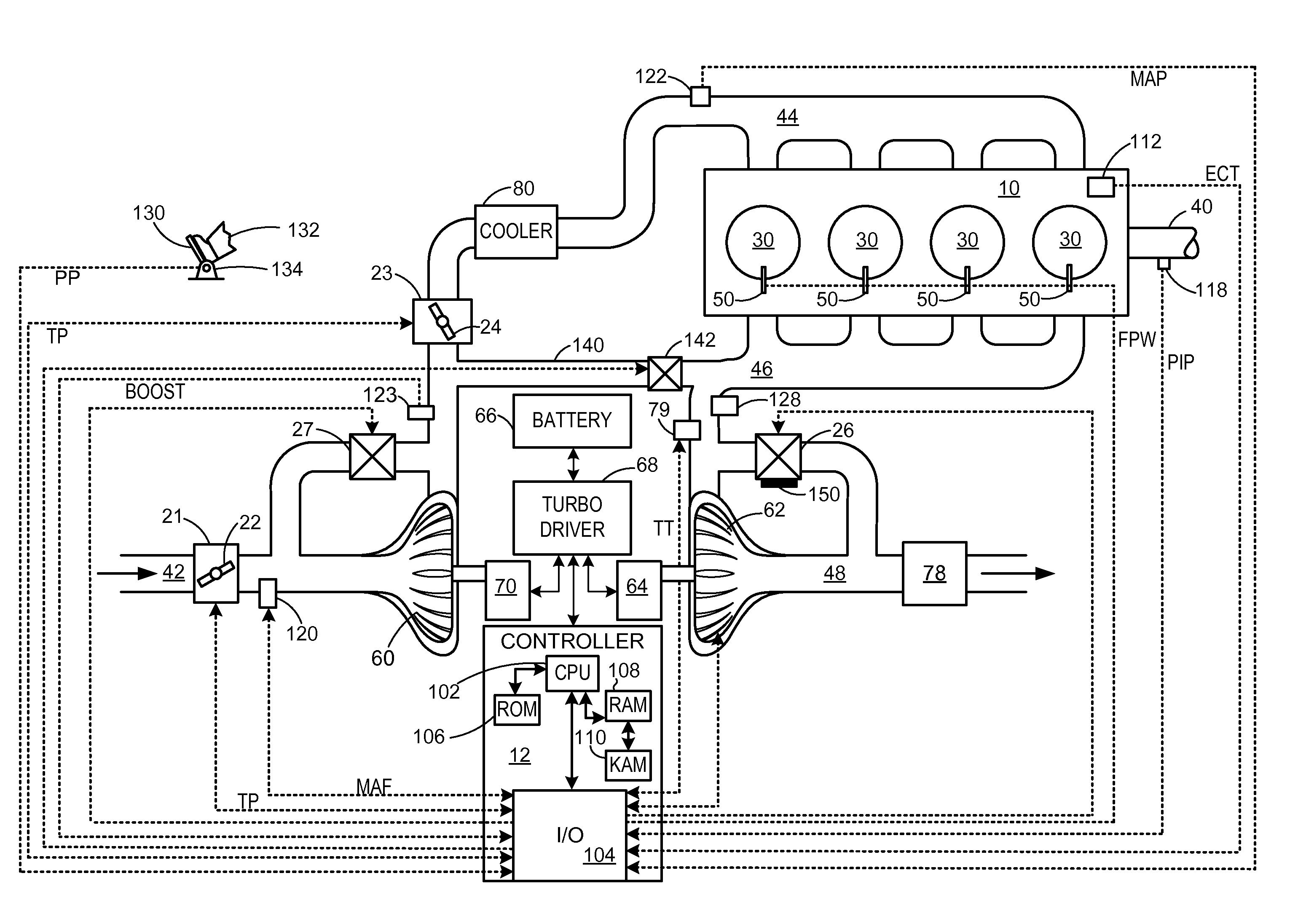
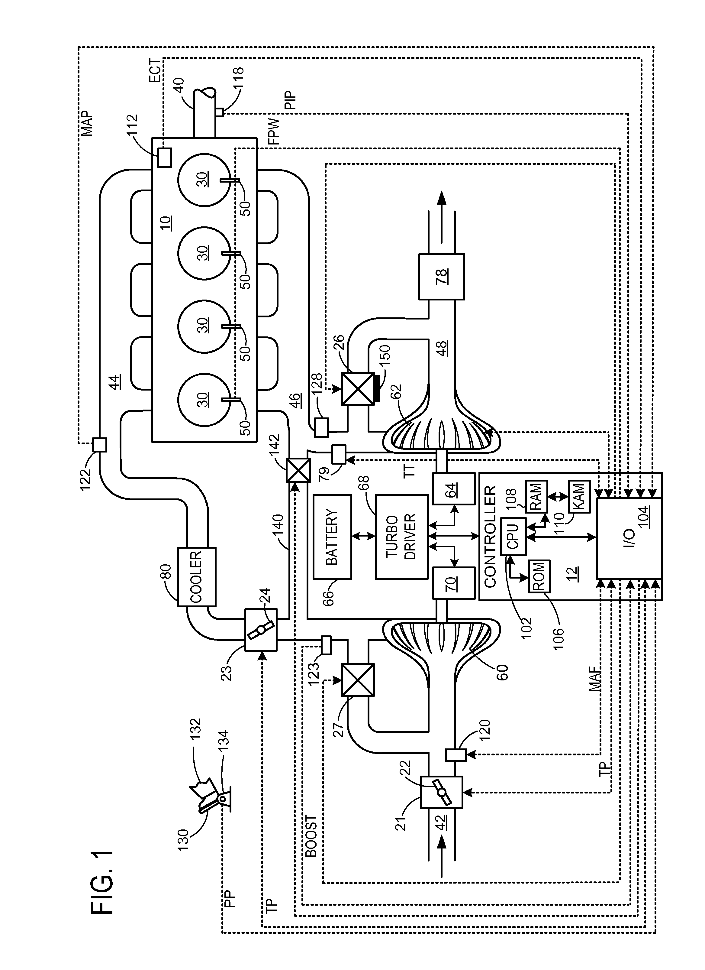
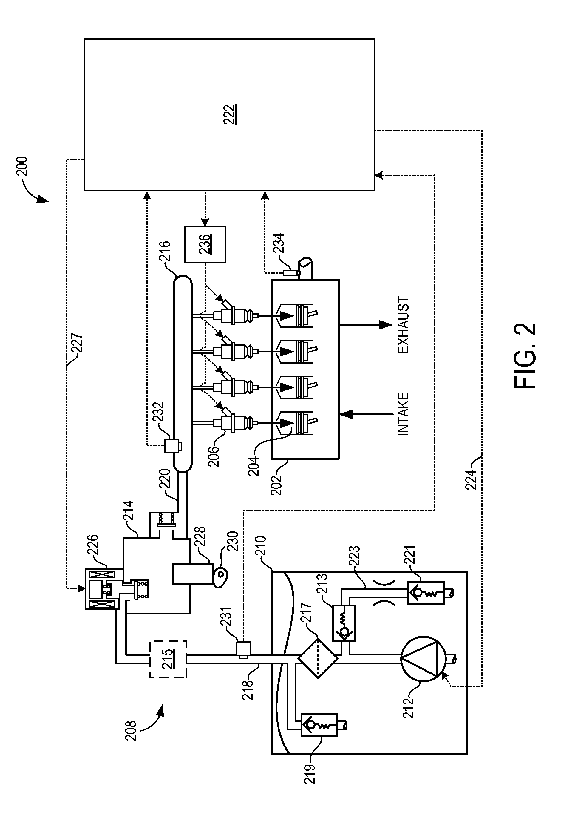
[0015]Methods and systems are provided for improving closed-loop lift pump pressure control in engines having fuel systems where a low pressure (LP) fuel lift pump draws pressurized fuel from a fuel tank and supplies the pressurized fuel to a high pressure (HP) fuel pump, as shown in FIGS. 1-2. The high pressure fuel pump may further raise the pressure of the pressurized fuel to a level sufficient for directly injecting fuel into the engine cylinders. A lift pump voltage may be commanded to provide a desired lift pump pressure, as shown in FIG. 3. To reduce fueling errors and potential engine stalls caused due to a falsely high output from a lift pump pressure sensor, a controller may clip the commanded lift pump voltage on the lower end during closed-loop fuel pump output control (FIG. 4). For example, the controller may be configured to perform a routine, such as the routine of FIG. 5, to apply a minimum pump voltage during conditions when the commanded lift pump voltage is below ...


PUM


Abstract

Methods and systems are provided for enforcing a minimum fuel lift pump commanded voltage that is determined as a function of commanded lift pump pressure and fuel flow rate. The minimum fuel lift pump voltage is applied when the commanded voltage is lower than the minimum voltage. The approach reduces engine stalls induced by ingestion of fuel vapors at an injection pump coupled downstream of the lift pump.

Description

FIELD[0001]The field of the disclosure generally relates to fuel systems in internal combustion engines.BACKGROUND AND SUMMARY[0002]Lift pump control systems may be used for a variety of fuel system control purposes. These may include, for example, vapor management, injection pressure control, temperature control, and lubrication. In one example, a lift pump supplies fuel to a high pressure fuel pump that provides a high injection pressure for direct injectors in an internal combustion engine. The high pressure fuel pump may provide the high injection pressure by supplying high pressure fuel to a fuel rail to which the direct injectors are coupled. A fuel pressure sensor may be disposed in the fuel rail to enable measurement of the fuel rail pressure, on which various aspects of engine operation may be based, such as fuel injection.[0003]However, the inventors herein have identified potential issues with such systems. Lift pump pressure sensors may degrade. In particular, they may f...

Claims


Application Information

Patent Timeline
Patent Type & Authority Applications(United States)
IPC IPC(8): F02D41/38F02D41/26F02D33/00F02D41/30
CPCF02D41/3854F02D33/003F02D41/26F02D41/3082F02D2200/0602F02M37/103F02D41/20F02D2041/2048F02D2041/2051F02D2041/223F02M51/00
Inventor PURSIFULL, ROSS DYKSTRA
Owner FORD GLOBAL TECH LLC
Why Eureka
Try Eureka