Waste Heat Accumulator/Distributor System

a technology of waste heat accumulator and distribution system, which is applied in the direction of indirect heat exchangers, machines/engines, light and heating apparatus, etc., can solve the problems of occupying a significant amount of packaging space for separate cooling systems, adding weight without benefit, etc., and achieves easy management of heat absorption between the different cooling loops, improved vehicle fuel economy, and dissipation of systems

Active Publication Date: 2011-09-08
GM GLOBAL TECH OPERATIONS LLC
View PDF28 Cites 28 Cited by
  • Summary
  • Abstract
  • Description
  • Claims
  • Application Information

AI Technical Summary

Benefits of technology

An advantage of an embodiment is that the waste heat accumulator / distributor system can selectively capture waste heat from the engine, powertrain electronics or transmission and transfer that heat to systems that have a current need for the thermal energy or the capacity to absorb the waste heat being generated and dissipate it out of the systems. The heat absorption between the different cooling loops can be easily managed by employing two electronically controlled valves in two of the three cooling loops and a single multi-fluid heat exchanger. This system may allow for improved vehicle fuel economy, improved electric only range of a vehicle, improved HVAC system operation, and improved vehicle packaging. Moreover, the cost of the transmission cooling system may be reduced by eliminating the need for a separate transmission fluid cooler.

Problems solved by technology

These separate cooling systems take up a significant amount of packaging space and add weight with no benefit of synergies since the three cooling systems are separate.

Method used


Image

  • Waste Heat Accumulator/Distributor System
  • Waste Heat Accumulator/Distributor System
  • Waste Heat Accumulator/Distributor System

Examples


Embodiment Construction

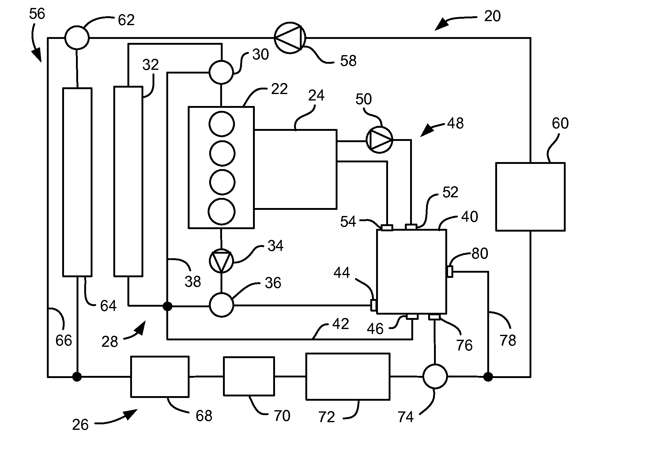
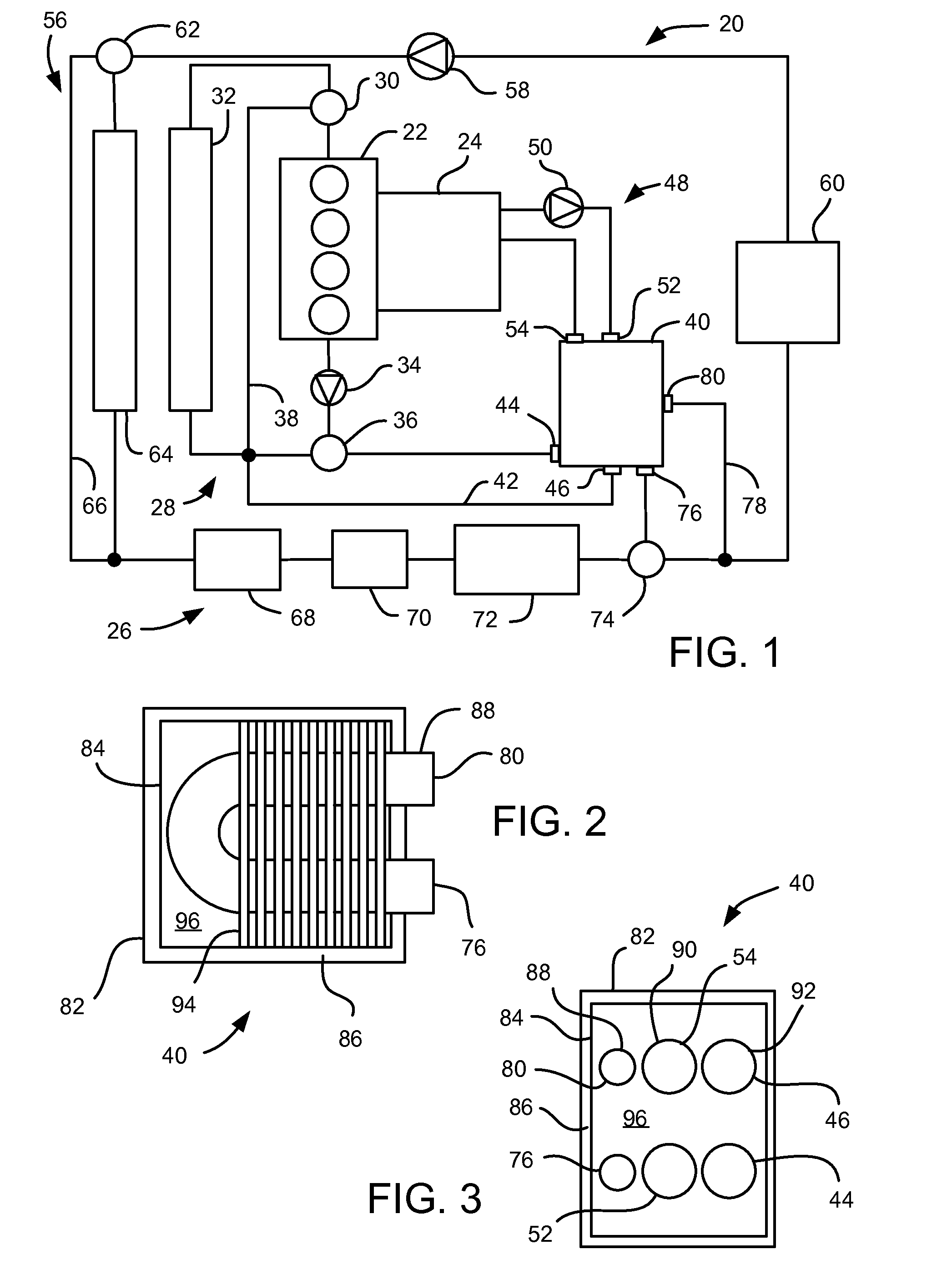
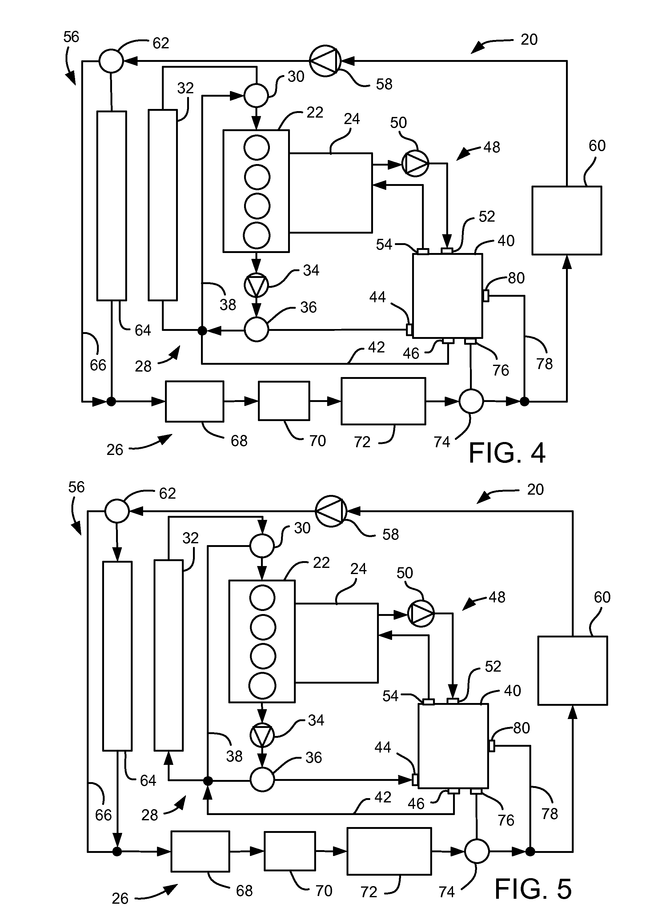
Referring to FIG. 1, a waste heat accumulator / distributor system 20 used in a vehicle is shown. The system 20 interacts with a power plant, such as, for example, an internal combustion engine 22, a transmission 24 and a powertrain electronics system 26. Such a system 20 may be employed in, for example, a hybrid electric or extended range electric vehicle.

The system 20 interfaces with the engine 22 via an engine coolant loop 28. The engine coolant loop 28 may include a thermostat 30, selectively directing engine coolant flow through or bypassing an engine radiator 32 based on the temperature of the engine coolant. The engine coolant loop also includes a water pump 34 for pumping the engine coolant through the loop 28. An electronically controlled valve 36 is in the engine coolant loop 28 and can be controlled to selectively direct the coolant flowing from the engine 22 toward the engine radiator 32 or radiator bypass line 38, or to direct the coolant flowing from the engine 22 toward...


PUM


Abstract

A waste heat accumulator/distributor system for use in a vehicle. The system includes an engine coolant loop directing engine coolant through a power plant, a powertrain electronics coolant loop directing electronics coolant through a powertrain electronics system; and a transmission fluid loop directing transmission fluid through a transmission. The system includes a multi-fluid heat exchanger including an engine coolant inlet receiving the engine coolant from the engine coolant loop, an electronics coolant inlet receiving the electronics coolant from the powertrain electronic coolant loop, and a transmission fluid inlet receiving the transmission fluid from the transmission fluid loop; a first valve controllable to cause engine coolant to flow into the engine coolant inlet or to bypass the engine coolant inlet; and a second valve controllable to cause electronics coolant to flow into the electronics coolant inlet or to bypass the electronics coolant inlet.

Description

BACKGROUND OF INVENTIONThe present invention relates generally to cooling systems for vehicle subsystems and more particularly to a waste heat accumulator / distributor system incorporated into vehicle cooling systems.Traditionally, vehicles employing internal combustion engines and automatic transmissions have separate cooling systems for the two vehicle subsystems. In the case of hybrid electric and extended range electric vehicles, often a third separate cooling system for the powertrain electronics is also employed. These separate cooling systems take up a significant amount of packaging space and add weight with no benefit of synergies since the three cooling systems are separate.SUMMARY OF INVENTIONAn embodiment contemplates a waste heat accumulator / distributor system for use in a vehicle. The system may include an engine coolant loop directing engine coolant through a power plant, a powertrain electronics coolant loop directing electronics coolant through a powertrain electroni...

Claims


Application Information

Patent Timeline
Patent Type & Authority Applications(United States)
IPC IPC(8): F01P7/16F01P1/06F28D15/00
CPCF01P1/06Y02E60/145F28D15/00F01P7/16F01P2060/045F01P3/20F01P2050/24B60H1/00492F01P2060/08F16H57/0417F28D2021/008B60H2001/00307F01P7/10F01P7/12F01P3/207F01P2050/04F01P2007/146B64D33/08F01P7/164F01P2025/32F01P7/165F01P7/023Y02E60/14
Inventor BENOIT, RYAN J.
Owner GM GLOBAL TECH OPERATIONS LLC
Why Eureka
Try Eureka