
Electric equipment in which heat being dissipated through superficial temperature maintaining member and exchanging fluid

Inactive Publication Date: 2012-04-26
YANG TAI HER
View PDF18 Cites 7 Cited by
  • Summary
  • Abstract
  • Description
  • Claims
  • Application Information

AI Technical Summary

Benefits of technology

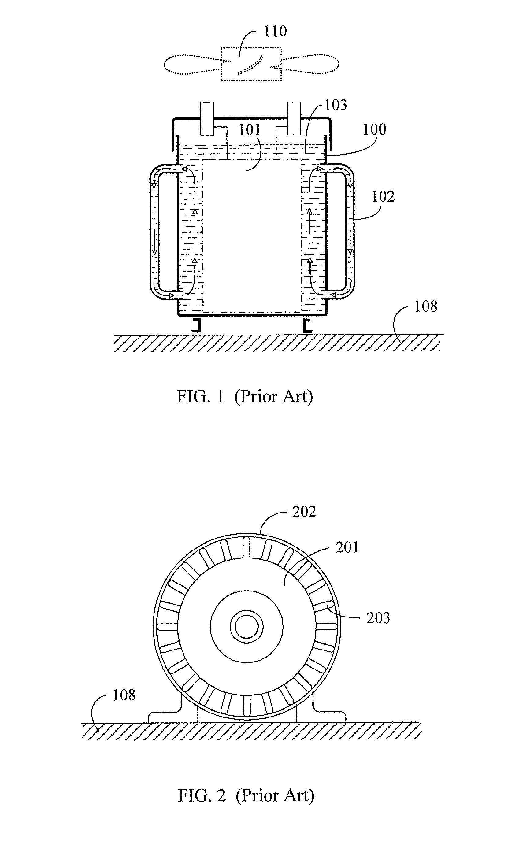
[0006]FIG. 1 is a schematic view showing the heat dissipation means of an electric transformer of conventional electrical equipment.
[0006]FIG. 1 is a schematic view showing the heat dissipation means of an electric transformer of conventional electrical equipment.
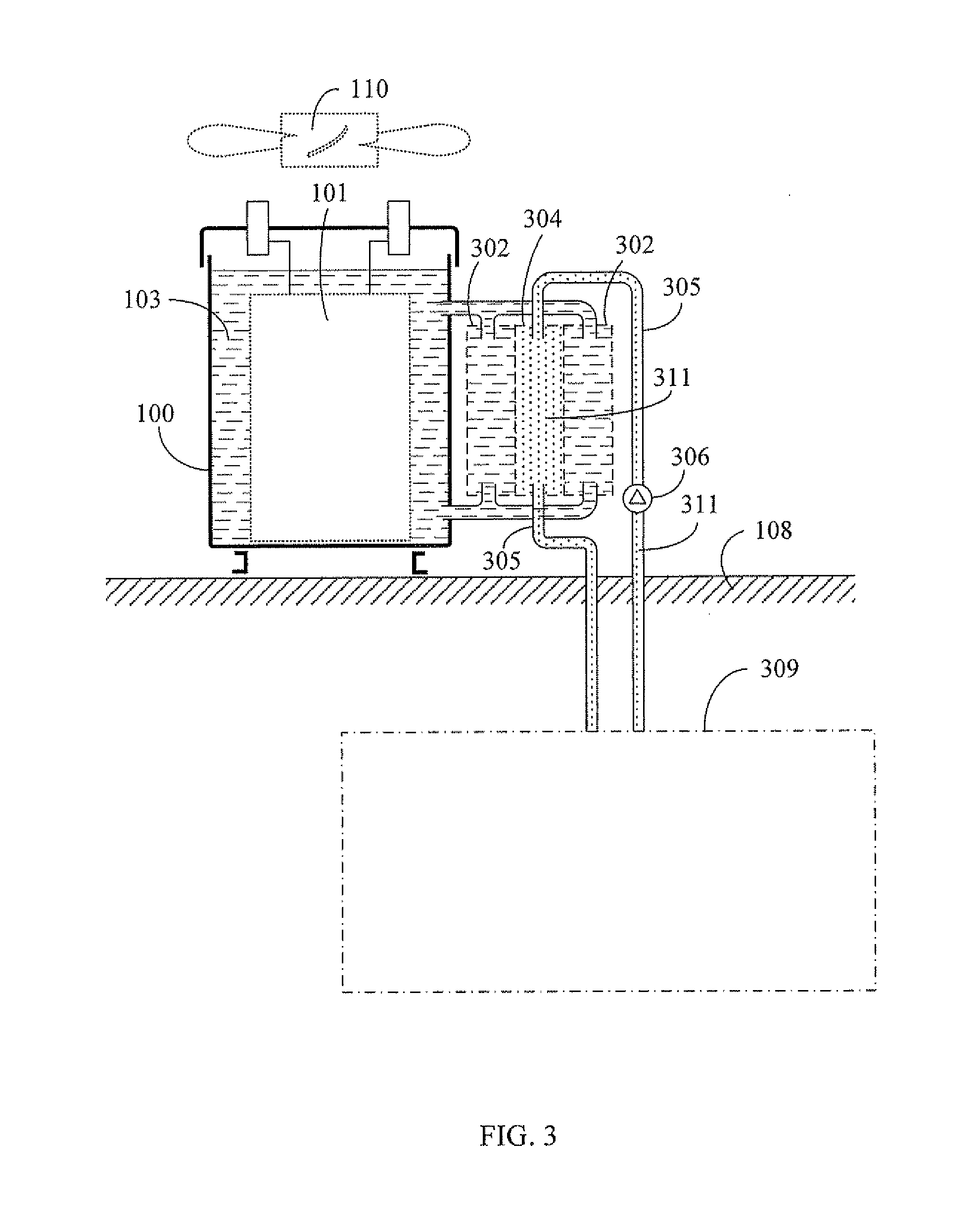
[0008]FIG. 3 is a schematic structural view showing the electric transformer installed with the superficial temperature maintaining member and the exchanging fluid according to the present invention.
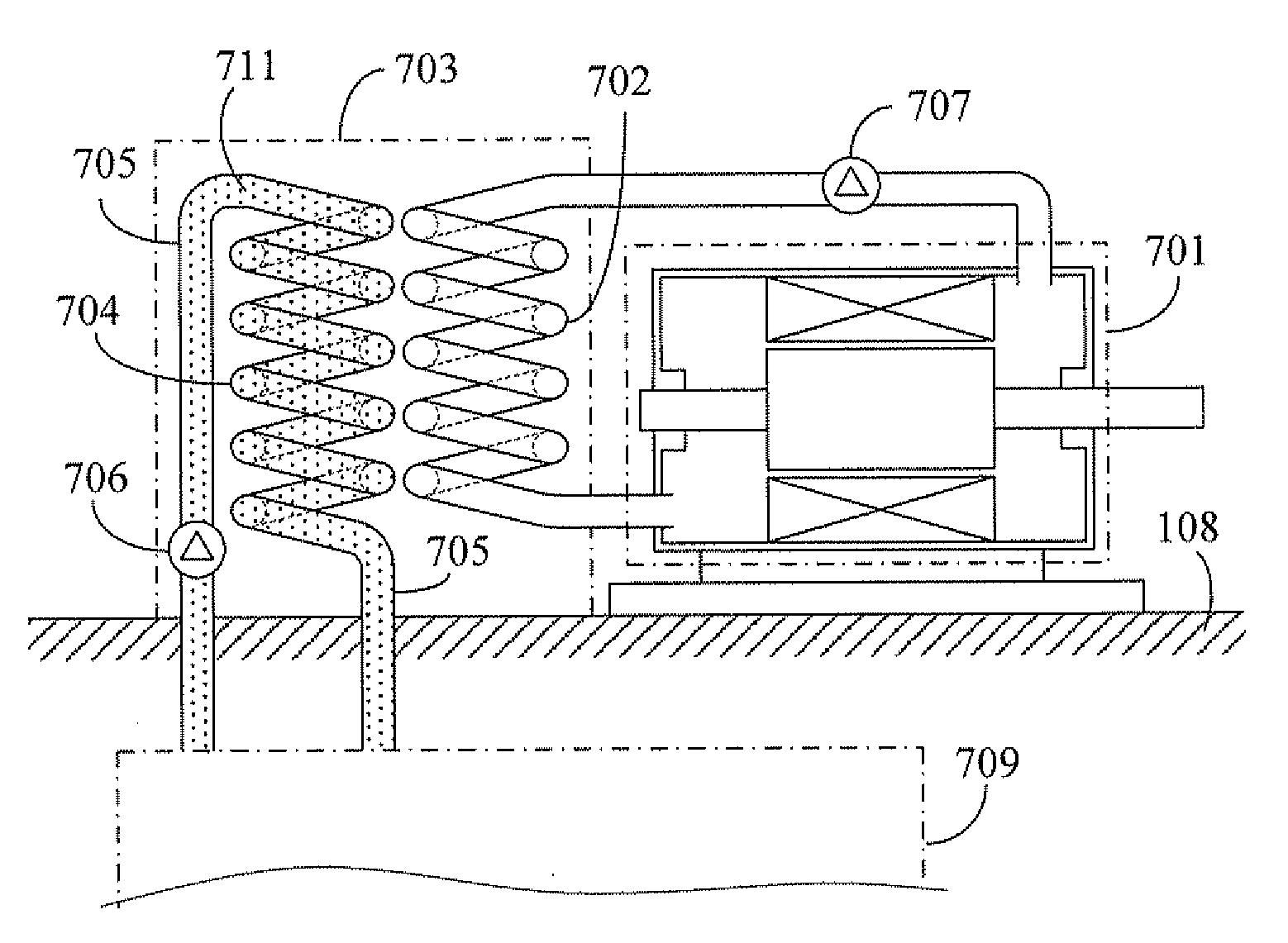
[0032]The present invention relates to a fluid heat exchange device installed at the exterior of an electrical equipment housing, and a primary pipeline of the heat exchange device and the cooling fluid inside the electrical equipment form a primary side fluid circulation loop, and a secondary pipeline of the heat exchange device and a heat equalizer installed in a superficial temperature maintaining member such as superficial ground, lake, pool or river pumping the fluid through the pump form a secondary side circulation loop, by means of the heat equalizer installed in the superficial temperature maintaining member to absorb the heat of the passing fluid with higher temperature so as to dissipate the heat of the electrical equipment;
[0032]The present invention relates to a fluid heat exchange device installed at the exterior of an electrical equipment housing, and a primary pipeline of the heat exchange device and the cooling fluid inside the electrical equipment form a primary side fluid circulation loop, and a secondary pipeline of the heat exchange device and a heat equalizer installed in a superficial temperature maintaining member such as superficial ground, lake, pool or river pumping the fluid through the pump form a secondary side circulation loop, by means of the heat equalizer installed in the superficial temperature maintaining member to absorb the heat of the passing fluid with higher temperature so as to dissipate the heat of the electrical equipment;
[0032]The present invention relates to a fluid heat exchange device installed at the exterior of an electrical equipment housing, and a primary pipeline of the heat exchange device and the cooling fluid inside the electrical equipment form a primary side fluid circulation loop, and a secondary pipeline of the heat exchange device and a heat equalizer installed in a superficial temperature maintaining member such as superficial ground, lake, pool or river pumping the fluid through the pump form a secondary side circulation loop, by means of the heat equalizer installed in the superficial temperature maintaining member to absorb the heat of the passing fluid with higher temperature so as to dissipate the heat of the electrical equipment;
[0032]The present invention relates to a fluid heat exchange device installed at the exterior of an electrical equipment housing, and a primary pipeline of the heat exchange device and the cooling fluid inside the electrical equipment form a primary side fluid circulation loop, and a secondary pipeline of the heat exchange device and a heat equalizer installed in a superficial temperature maintaining member such as superficial ground, lake, pool or river pumping the fluid through the pump form a secondary side circulation loop, by means of the heat equalizer installed in the superficial temperature maintaining member to absorb the heat of the passing fluid with higher temperature so as to dissipate the heat of the electrical equipment;

Problems solved by technology

A conventional electrical equipment includes a fixed electric transformer or rotary power generator or motor or electric turbine brake device; when an electrical equipment is powered and operated, the heat is generated through copper loss of electric conductive member or iron loss of magnetic conductive member, and the heat is accumulated and temperature is raised with time goes by, so the efficiency and service life of the electrical equipment are affected or the electrical equipment would even be damaged.

Method used


Image

  • Electric equipment in which heat being dissipated through superficial temperature maintaining member and exchanging fluid
  • Electric equipment in which heat being dissipated through superficial temperature maintaining member and exchanging fluid
  • Electric equipment in which heat being dissipated through superficial temperature maintaining member and exchanging fluid

Examples


Embodiment Construction

[0031]A conventional electrical equipment includes a fixed electric transformer or rotary power generator or motor or electric turbine brake device; when an electrical equipment is powered and operated, the heat is generated through copper loss of electric conductive member or iron loss of magnetic conductive member, and the heat is accumulated and temperature is raised with time goes by, so the efficiency and service life of the electrical equipment are affected or the electrical equipment would even be damaged;

[0032]The present invention relates to a fluid heat exchange device installed at the exterior of an electrical equipment housing, and a primary pipeline of the heat exchange device and the cooling fluid inside the electrical equipment form a primary side fluid circulation loop, and a secondary pipeline of the heat exchange device and a heat equalizer installed in a superficial temperature maintaining member such as superficial ground, lake, pool or river pumping the fluid th...


PUM


Abstract

The present invention relates to a heat exchange device equipped with a primary fluid circulation loop and a secondary fluid circulation loop and installed between an electrical equipment and a superficial temperature maintaining member, such that the heat generated by the electrical equipment is transmitted by a primary side fluid of the heat exchange device, and a secondary side fluid passes through a heat equalizer installed in the superficial temperature maintaining member so as to dissipate heat through the superficial temperature maintaining member.

Description

BACKGROUND OF THE INVENTION[0001](a) Field of the Invention[0002]The present invention relates to a fluid heat exchange device installed at the exterior of an electrical equipment housing, and a primary pipeline of the heat exchange device and the cooling fluid inside the electrical equipment form a primary side fluid circulation loop, and a secondary pipeline of the heat exchange device and a heat equalizer installed in a superficial temperature maintaining member such as superficial ground, lake, pool or river pumping the fluid through the pump form a secondary side circulation loop, by means of the heat equalizer installed in the superficial temperature maintaining member to absorb the heat of the passing fluid with higher temperature so as to dissipate the heat of the electrical equipment.[0003](b) Description of the Prior Art[0004]A conventional electrical equipment includes a fixed electric transformer or rotary power generator or motor or electric turbine brake device; when a...

Claims


Application Information

Patent Timeline
IPC IPC(8): H05K7/20F24V50/00
CPCF28D15/00H02K9/19H01F27/12F28D20/0052H02K5/203F04D31/00H05K7/20F24H1/20
Inventor YANG, TAI-HER
Owner YANG TAI HER
Learn More