Gas segregator barrier for electrical switching apparatus

a technology of electrical switching apparatus and gas segregation barrier, which is applied in the direction of circuit-breaking switches, circuit-breaking switches for excess current, protective switch details, etc., can solve the problems of phase-to-phase electrical fault, phase-to-ground failure, electrical faults on the line side of circuit breakers, etc., and achieve the effect of reducing the number of electrical faults associated

Inactive Publication Date: 2005-08-02
EATON INTELLIGENT POWER LTD
View PDF8 Cites 30 Cited by
  • Summary
  • Abstract
  • Description
  • Claims
  • Application Information

AI Technical Summary

Benefits of technology

[0013]These needs and others are satisfied by the present invention, which is directed to a gas segregator barrier for electrical switching apparatus of a panelboard assembly. The barrier quenches and controllably directs ionized gases discharged from exhaust vent openings in the electrical switching apparatus, in order to minimize electrical faults associated therewith.

Problems solved by technology

Such ionized gases are typically discharged through vents in the molded plastic housing and, when discharged from one of the closely aligned circuit breakers within the double-branch arrangement, could transfer to the other circuit breaker, resulting in a phase-to-phase electrical fault.
The ionized gases could also cause a phase-to-ground failure with any metallic enclosure within which the circuit breaker is mounted.
This can lead to electrical faults on the line side of the circuit breakers and damage to switchgear equipment.
However, over long periods of continuous use, the fiber material can become brittle and deteriorate.
Additionally, because such fiberboard barriers are removable for access to the line terminals, subsequent connection of the circuit breakers to line terminal straps without replacing the barrier is possible, thus creating a path for ionized gases to potentially cause a phase-to-phase and / or phase-to-ground electrical fault.
Although the disclosed barrier insulates the line strap connectors, discharged ionized gases are not segregated or controllably directed.

Method used


Image

  • Gas segregator barrier for electrical switching apparatus
  • Gas segregator barrier for electrical switching apparatus
  • Gas segregator barrier for electrical switching apparatus

Examples


Embodiment Construction

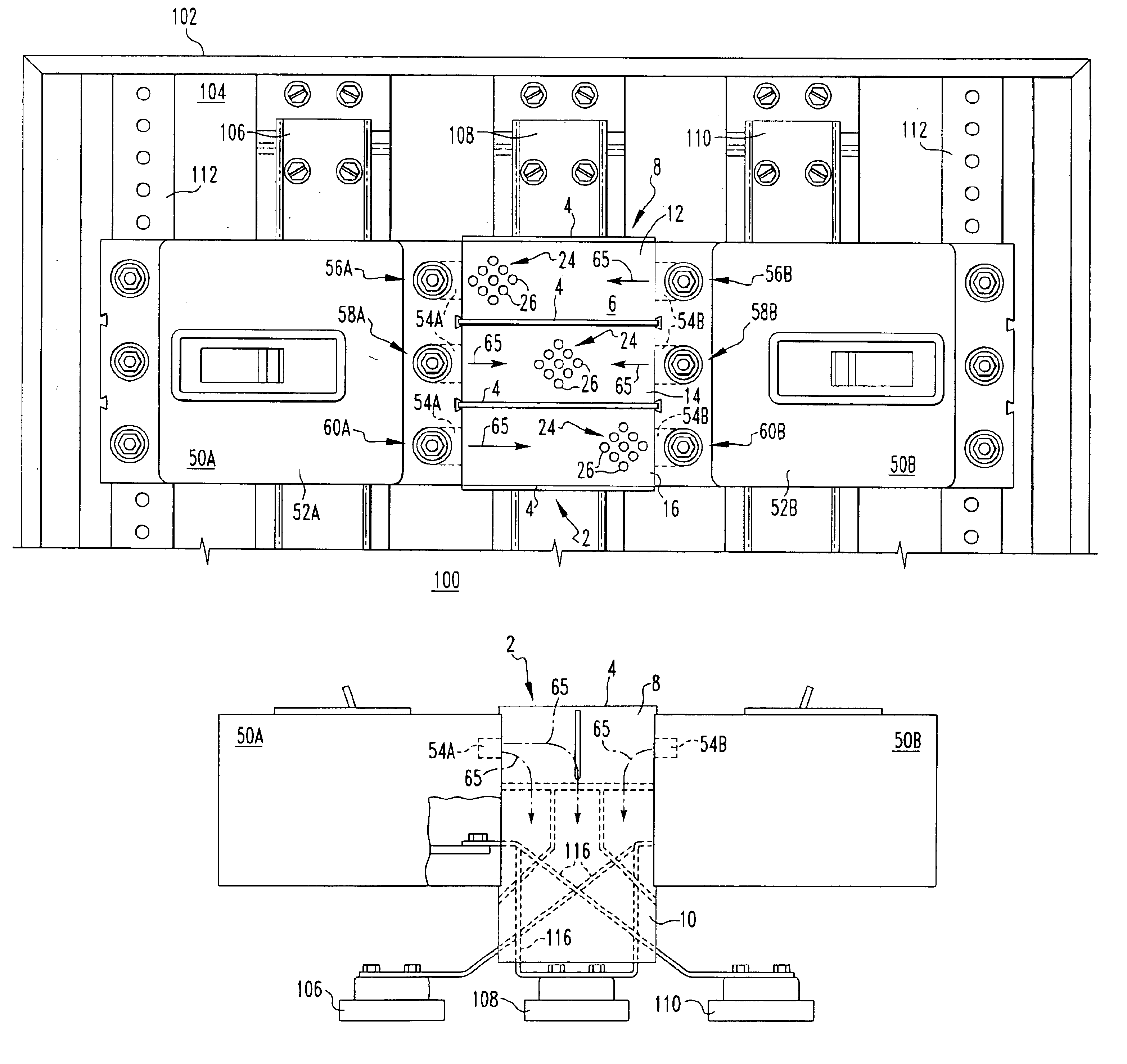
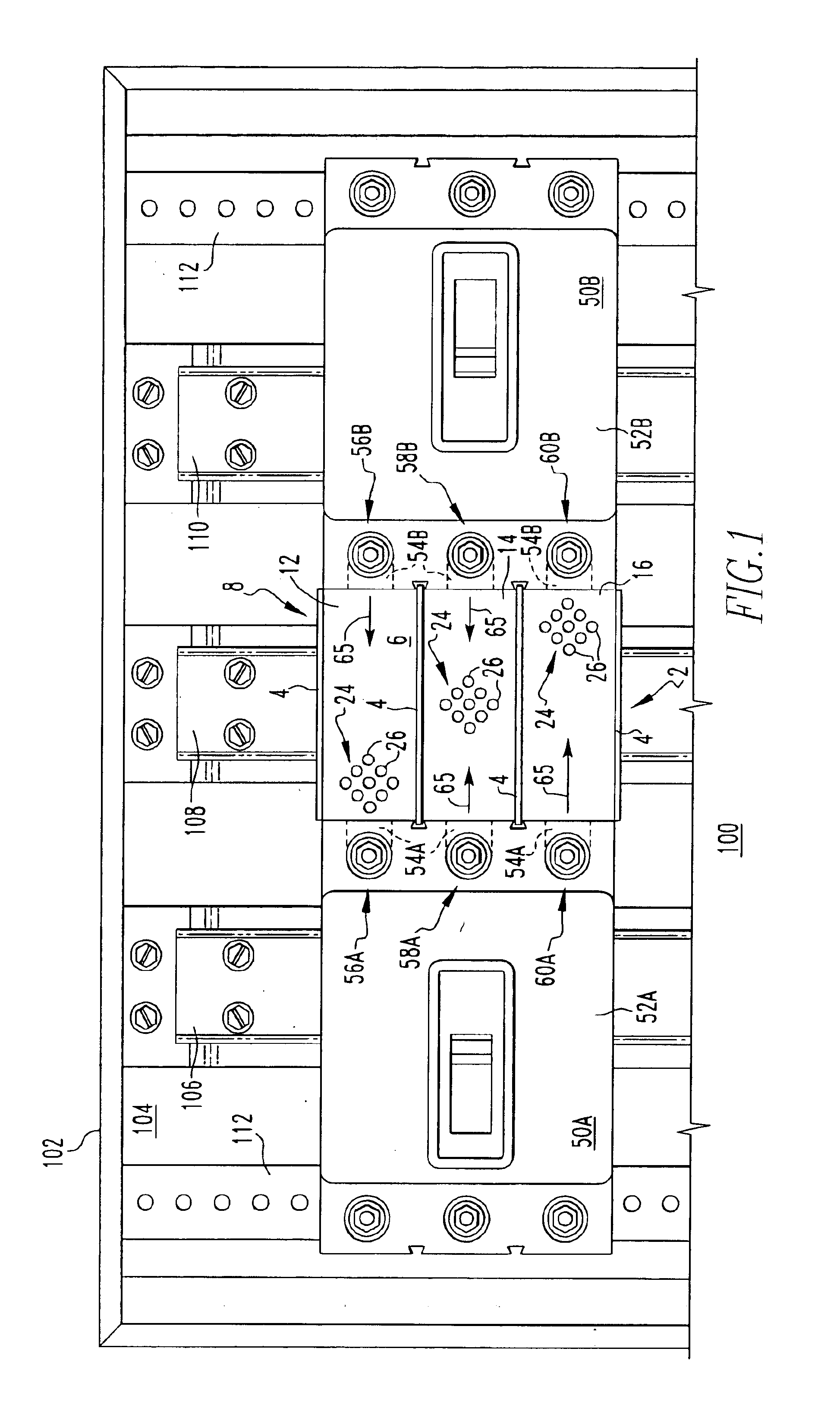
[0027]For purposes of illustration, the present invention will be described as applied to a panelboard assembly including one or more pairs of spaced-apart, three-pole circuit breakers, although it will become apparent that it could also be applied to other electrical power applications including other types of electrical switching apparatus such as, for example, load centers or similar power distribution devices used in residential, industrial and commercial applications and including electrical switching apparatus such as, for example, circuit switching devices, and other circuit interrupters such as contactors, motor starters, motor controllers, and other load controllers having one or more poles.

[0028]As employed herein, the term “ionized” means completely or partially converted into ions and being electrically conductive such as, for example, ionized gases generated in response to an electrical fault.

[0029]As employed herein, the term “switchgear cabinet” refers to the cabinet ...


PUM


Abstract

A gas segregator barrier is for quenching, segregating and controllably directing ionized gases discharged from a pair of spaced-apart circuit breakers double-branch mounted within a panelboard assembly. The spaced-apart circuit breakers include corresponding pairs of opposing poles, and a housing with exhaust vent openings for discharging ionized gases developed from an electrical fault. The gas segregator barrier includes at least substantially parallel segregator fins divided into first and second portions by a transverse dividing member. Baffles in the transverse dividing member quench the ionized gases and provide fluid communication between exhaust channels formed between the segregator fins of the first portion, and gas ducts disposed between the segregator fins of the second portion. The gas ducts include one or more lateral members structured to controllably direct the discharged ionized gases.

Description

BACKGROUND OF THE INVENTION[0001]1. Field of the Invention[0002]The present invention relates generally to panelboard assemblies and, more particularly, to a panelboard assembly employing a gas segregator barrier for avoiding inadvertent flow of electrical current due to ionized exhaust gases being discharged from electrical switching apparatus therein. The invention also relates to gas segregator barriers for electrical switching apparatus.[0003]2. Background Information[0004]Panelboard assemblies are power distribution devices used in residential, industrial and commercial applications. Panelboards typically comprise a wall mounted box enclosure supporting conductive bus bars and electrical switching apparatus (e.g., without limitation, circuit switching devices and circuit interrupters such as circuit breakers, contactors, motor starters, motor controllers and other load controllers) electrically connected to the bus bars.[0005]Panelboard assemblies often include pairs of adjacen...

Claims


Application Information

Patent Timeline
Patent Type & Authority Patents(United States)
IPC IPC(8): H01H9/34H01H9/30H02B1/015H02B1/06H01H71/02H01H9/02
CPCH01H9/342H02B1/06H01H9/0264H01H71/0264H02B13/025
Inventor AFSHARI, FARHADOLSZEWSKI, DAVID M.BEATTY, JR., WILLIAM E.CROOKS, WILLIAM M.RANDAL, WILLIAM M.HAAG, DAVID K.
Owner EATON INTELLIGENT POWER LTD
Why Eureka
Try Eureka