Distributed energy neural network integration system

a neural network and distributed energy technology, applied in the field of distributed energy neural network integration system, can solve the problems of large unfavorable renewable energy generation,

Inactive Publication Date: 2005-08-02
ORION ENG
View PDF9 Cites 147 Cited by
  • Summary
  • Abstract
  • Description
  • Claims
  • Application Information

AI Technical Summary

Problems solved by technology

Attempts to implement renewable energy generation were largely unsuccessful.
The monopoly-induced constraint that generation occur in a single location created large, unwieldy systems that were not cost effective.
An important provision to PURPA requiring utilities to buy power from Non-Utility Generators (NUG) was hugely unpopular with utilities be

Method used


Image

  • Distributed energy neural network integration system
  • Distributed energy neural network integration system
  • Distributed energy neural network integration system

Examples


Embodiment Construction

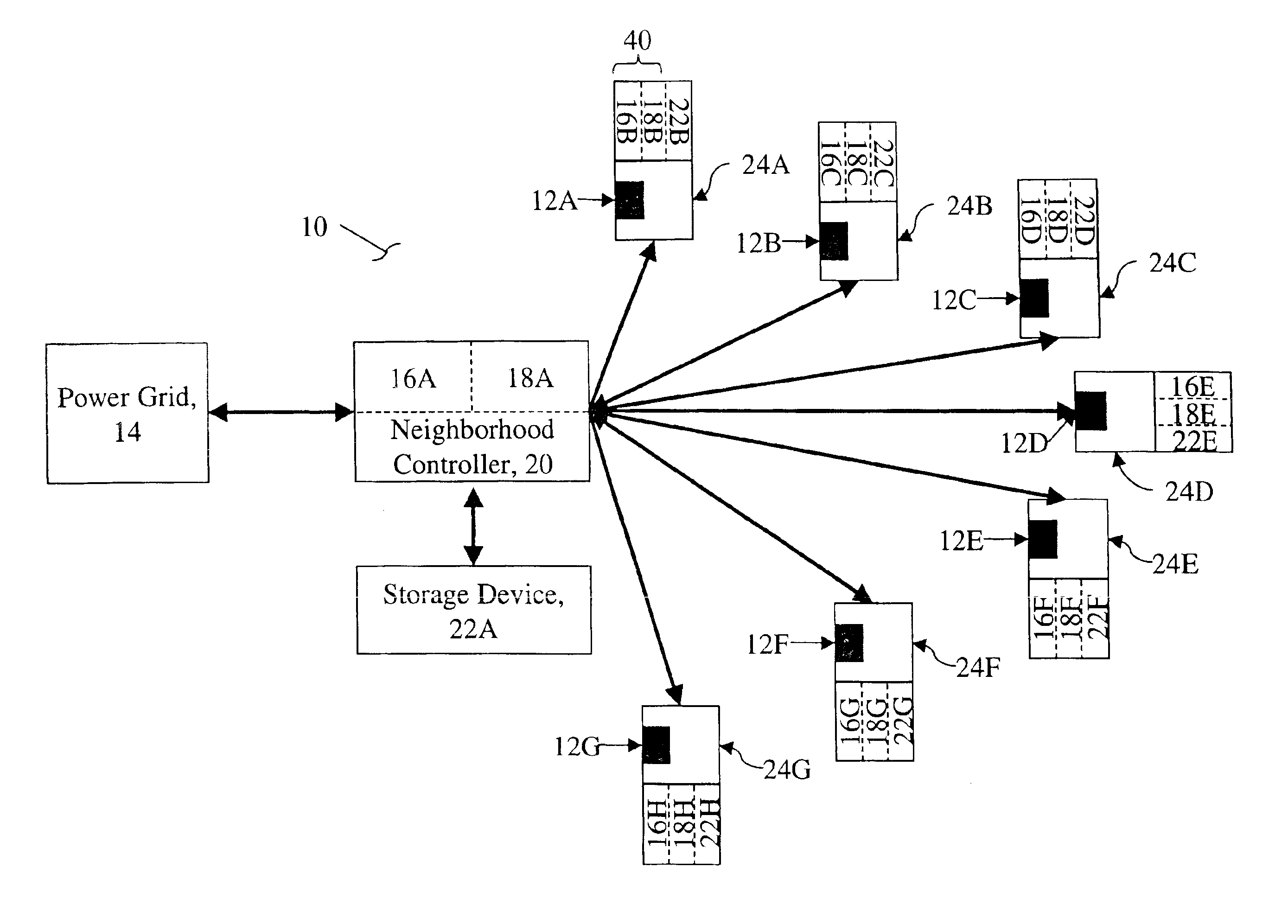
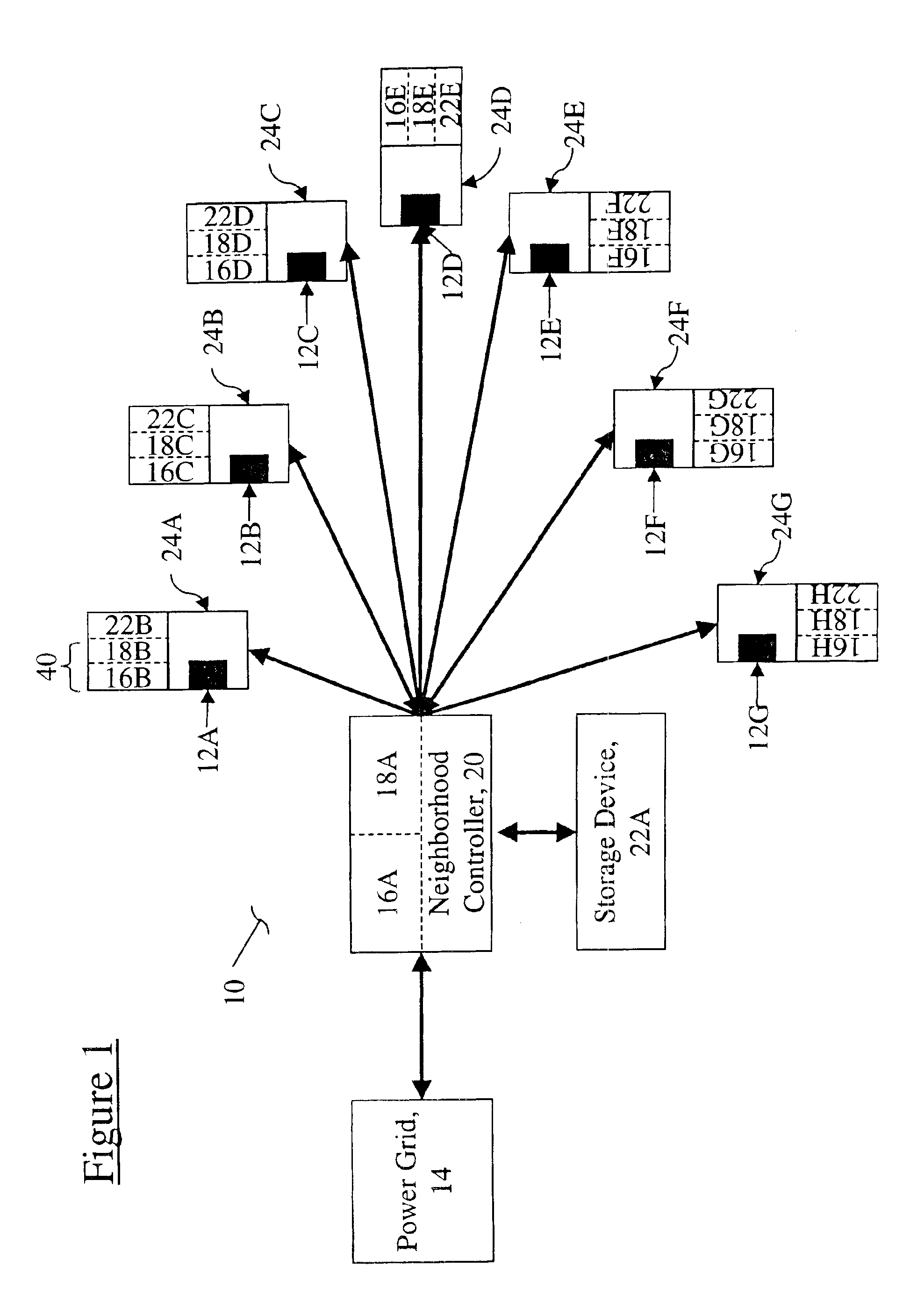
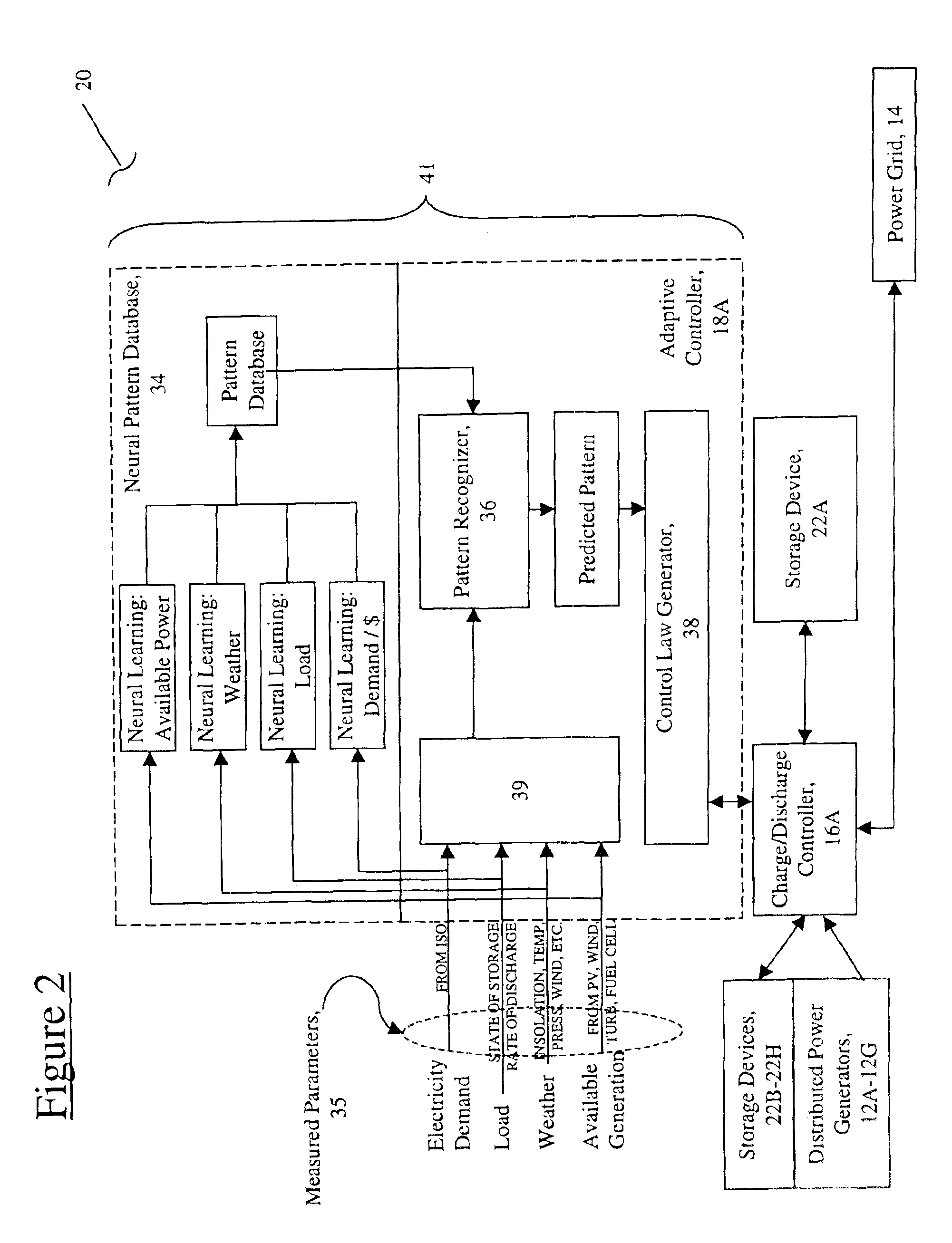
[0015]FIG. 1 shows a block diagram of an apparatus 10 for operably coupling a plurality of distributed power generators 12A, 12B, 12C, •12D, 12E, 12F and 12G to an electrical power grid 14. The apparatus 10 includes a charge / discharge controller 16 (illustrated at various exemplary locations designed as 16A-16H, and identified generically as item 16) and an adaptive controller 18 (illustrated at various exemplary locations designated as 18A-18H, and identified generically as item 18). The charge / discharge controller 16 transfers energy generated by the plurality of distributed power generators (selected from 12A-12G) to the power grid 14. The adaptive controller 18 directs when the charge / discharge controller 16 transfers energy generated by at least one of the plurality of distributed power generators 12A-12G to the power grid 14. The adaptive controller 18 directs the controller 16 based upon at least one selected parameter 35 from the measured parameters of FIG. 2. In operation, ...


PUM


Abstract

A system that couples distributed power generators together as a collective unit for the purposes of selling or purchasing energy from the electrical power grid. The apparatus includes a charge/discharge controller and an adaptive controller. The charge/discharge controller transfers energy generated by the plurality of distributed power generators to the power grid. The adaptive controller directs when the charge/discharge controller transfers energy generated by at least one of the plurality of distributed power generators to the electrical grid.

Description

DISTRIBUTED ENERGY NEURAL NETWORK INTEGRATION SYSTEMREFERENCE TO RELATED APPLICATIONS[0001]This application claims the benefit of U.S. Provisional Application No. 60 / 168,003, filed Nov. 30, 1999, the contents of which are incorporated herein by reference.BACKGROUND OF THE INVENTION[0002]Deregulation is rapidly transforming the monopoly structure of the U.S. electric power market. The mid to late 1990s saw renewables ushered into the power market for the first time in substantial quantity. Until 1995, utilities were structured around massive, central generating plants. Power was distributed to individual consumers through an elaborate network of power lines. Attempts to implement renewable energy generation were largely unsuccessful. The monopoly-induced constraint that generation occur in a single location created large, unwieldy systems that were not cost effective.[0003]In response to oil supply crunches throughout the 1970s, Congress passed the Public Utility Regulatory Policies ...

Claims


Application Information

Patent Timeline
IPC IPC(8): G06F19/00G06N3/04
CPCG06N3/0436G06N3/043
Inventor SINNOCK, HERBERT JAMES
Owner ORION ENG
Why Eureka
Try Eureka