
Direct drive distributed generator integrated with stayed rotor

Inactive Publication Date: 2011-12-22
CLIPPER WINDPOWER INC
View PDF4 Cites 19 Cited by
  • Summary
  • Abstract
  • Description
  • Claims
  • Application Information

AI Technical Summary

Benefits of technology

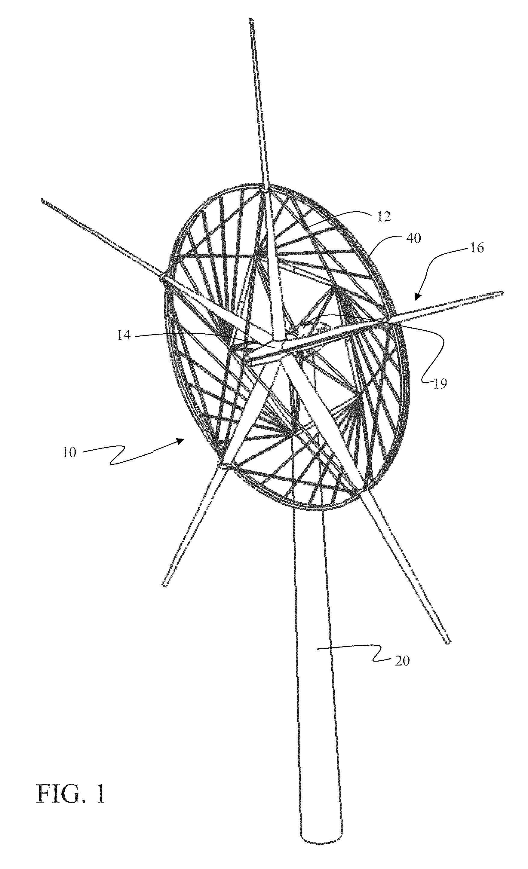
[0007]Exemplary embodiments provide a wind turbine power generation system incorporating a turbine rotor having a plurality of blades extending from a hub with each blade having an inner blade and an outer blade. A collar is provided on each blade with the inner blade extending between the hub and collar and the outer blade extending from the collar. A generator ring is carried by the collars and includes a generator rotor attached to the collars to rotate with the turbine rotor. A stator ring is supported from the generator rotor by a low friction interface with stationary positioning against the rotation of the generator rotor. A torque stay system prevents rotation of the stator ring for generation of power from the rotating turbine rotor as a linear distributed generator.

Problems solved by technology

While there are gearbox designs suitable for the low RPM and high torque characteristic of very large wind turbines, these are large, complex heavy machines that require a very high degree of precision in manufacturing and assembly, and where component change-out in the field or offshore can be problematic.

Method used


Image

  • Direct drive distributed generator integrated with stayed rotor
  • Direct drive distributed generator integrated with stayed rotor
  • Direct drive distributed generator integrated with stayed rotor

Examples


Embodiment Construction

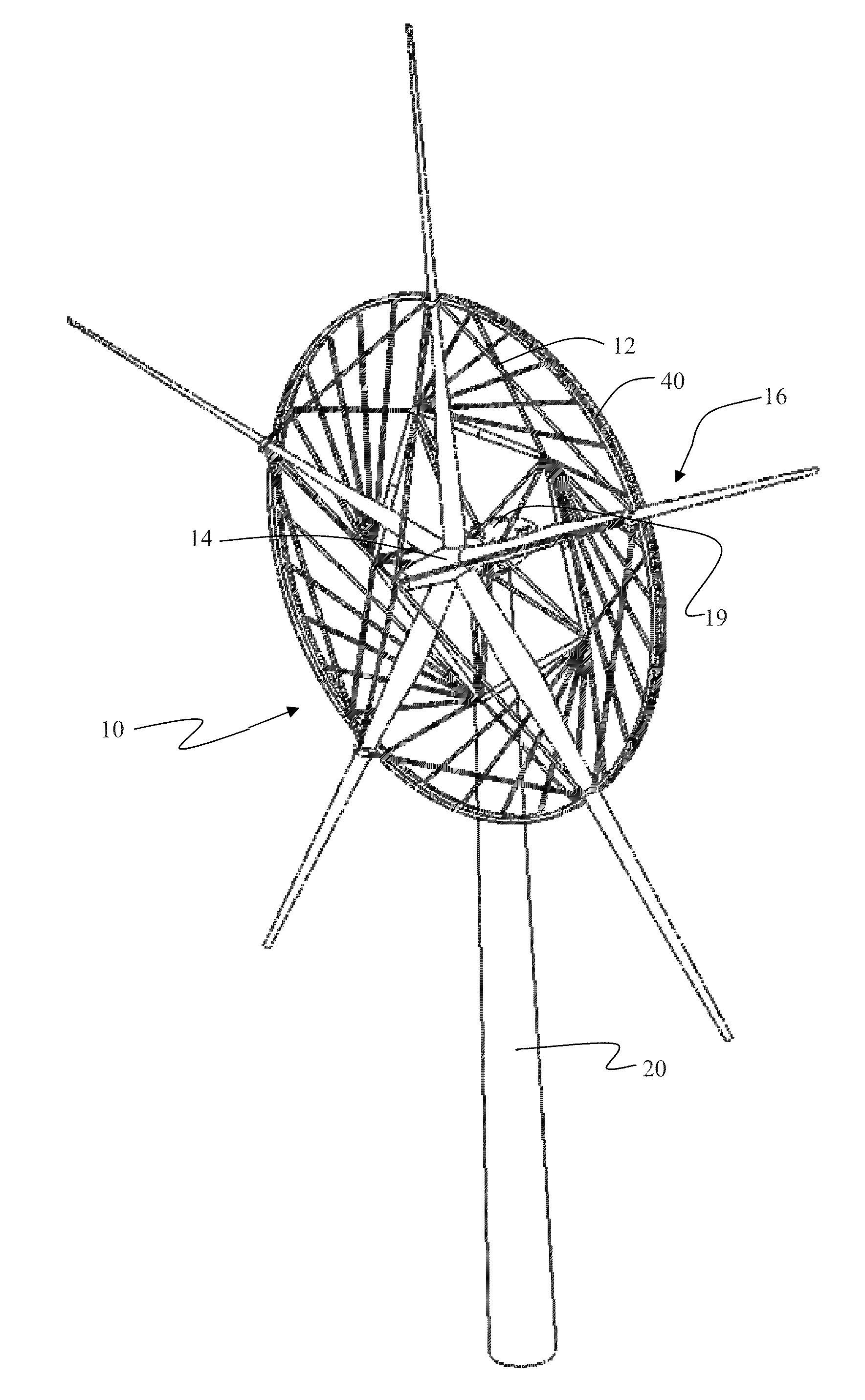
[0022]Embodiments of the invention incorporate a very large scale (˜10 MW) wind turbine multi-blade rotor 10 as shown in FIG. 1. Each blade 16 is constrained through a system of stay cables 12 from a rotor hub 14 attaching to a point ⅓ to ½ of the length of each blade from the hub. A collar 18 on each blade provides the attachment points for the stay cable system as will be described in greater detail subsequently. Each collar is also connected by stay cables to the adjoining blades' collars. A bearing system in the collar allows for the blade to have full pitch movement. The cable-stayed blade enables much greater swept area and lower cost than is currently possible with blades joined solely at the blade root to the hub. The rotor is supported by a nacelle 19 mounted from the ground by a tower 20.

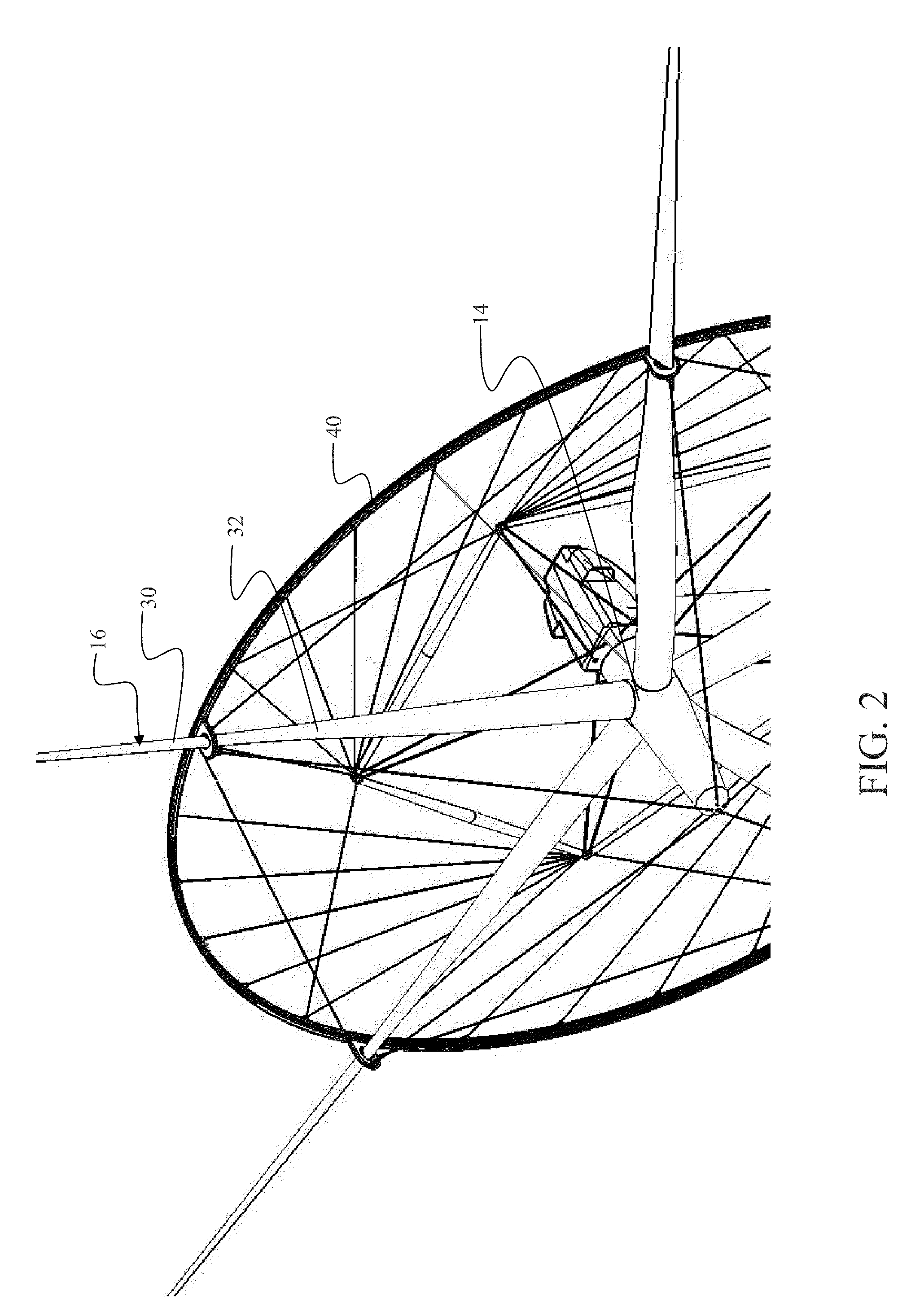
[0023]As seen in FIGS. 2 and 3, each collar 18 incorporates a first attach point 22 for a forestay cable 24 and opposing side attach points 26 for interblade lead and lag stay cables 28, 2...


PUM


Abstract

A wind turbine power generation system incorporates a turbine rotor having a plurality of blades extending from a hub with each blade having an inner blade and an outer blade. A collar is provided on each blade with the inner blade extending between the hub and collar and the outer blade extending from the collar. A generator ring is carried by the collars and includes a generator rotor attached to the collars to rotate with the turbine rotor. A stator ring is supported from the generator rotor by a low friction interface for relative rotation with the generator rotor. A torque stay system prevents rotation of the stator ring for generation of power from the rotating turbine rotor as a linear distributed generator.

Description

BACKGROUND[0001]1. Field[0002]This application relates generally to the field of large rotor turbines for wind power generation and more particularly to a structure for a large diameter direct drive generator integrated with a stayed wind turbine rotor.[0003]2. Related Art[0004]Wind turbines that reach multi-megawatt scale have large diameter low speed rotors (8-15 RPM). Typically, such wind turbines require a high step-up in rotational speed through a gearbox to provide economic generator and system efficiency. While there are gearbox designs suitable for the low RPM and high torque characteristic of very large wind turbines, these are large, complex heavy machines that require a very high degree of precision in manufacturing and assembly, and where component change-out in the field or offshore can be problematic. Some multi-megawatt wind turbines use a direct drive generator, which requires a large diameter (10M+) generator to attain gap speed sufficient for economic operation. Pr...

Claims


Application Information

Patent Timeline
IPC IPC(8): F03D9/00F03D1/06B64C27/00H02K7/102
CPCF03D1/0666F05B2220/7066Y02E10/725Y02E10/721H02K7/1869Y02E10/72F03D1/0658
Inventor DEHLSEN, JAMES G.P.FLEMING, ALEXDEHLSEN, JAMES B.
Owner CLIPPER WINDPOWER INC
Learn More