Edging roller

a technology of edging rollers and rollers, which is applied in the field of paint rollers, can solve the problems of difficult grasping and manipulating the positioning of shields, tedious and time-consuming use of rollers, and inconvenient use of conventional rollers

Inactive Publication Date: 2005-08-09
NEWELL OPERATING COMPANY
View PDF25 Cites 37 Cited by
  • Summary
  • Abstract
  • Description
  • Claims
  • Application Information

AI Technical Summary

Problems solved by technology

Although well-suited for applying paint to large expansive areas, such conventional rollers are not well-suited for applying paint to corners, to junctions between adjacent walls, along window trim, or along floor moldings, without smearing paint on the adjacent surface.
Although representing an advance in the art, such rollers are tedious and time consuming to use because repeated loading of the paint roller requires repeated detachment and attachment of the shield to and from the roller.
Although facilitating paint loading, such paint rollers have their associated drawbacks as well.
For example, such shields or guards are typically supported by an arm which is difficult to grasp and manipulate positioning of the shield without the painter's hands becoming covered with paint.
In addition, such rollers require that the roller and adjacent shield be pressed towards the surface being painted with a relatively large amount of force to apply paint as close as possible to the adjacent surface such as trim.
Moreover, such paint rollers are often fatiguing to use and aesthetically unattractive.
In addition to having the aforementioned problems, the applicator having a roller that rotates away from the shield frequently results in paint splattering.

Method used


Image

  • Edging roller
  • Edging roller
  • Edging roller

Examples


Embodiment Construction

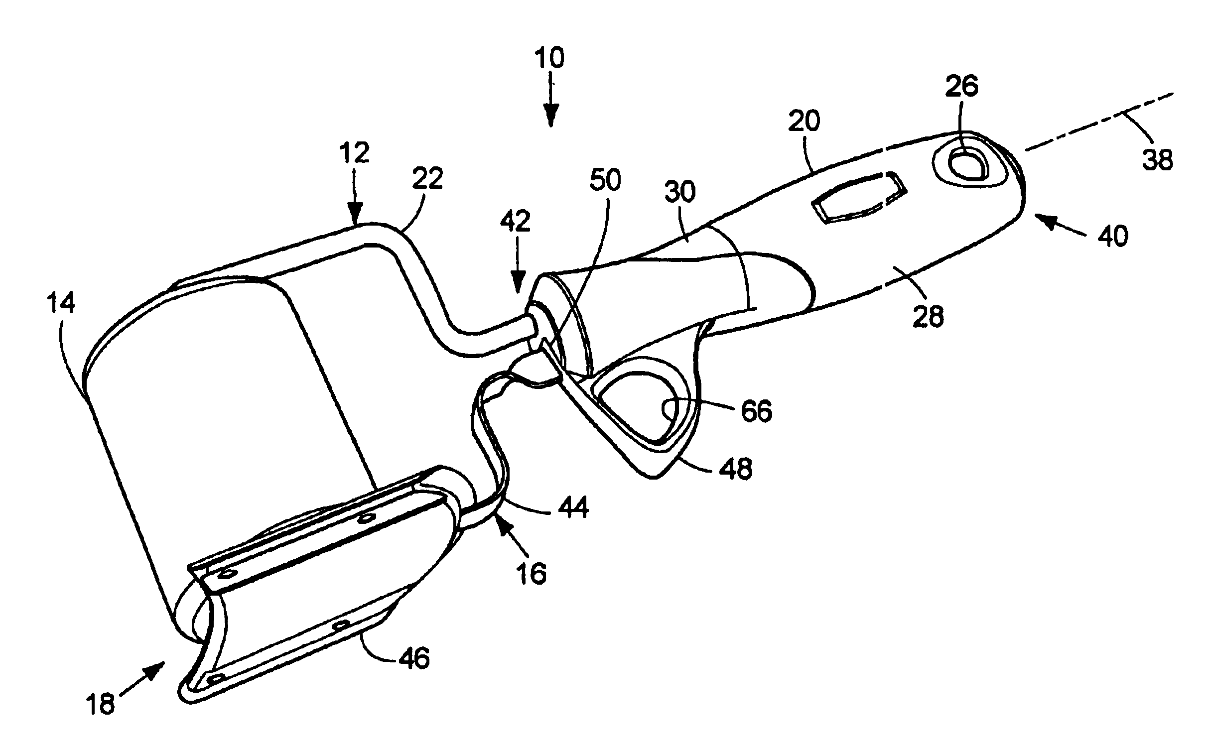
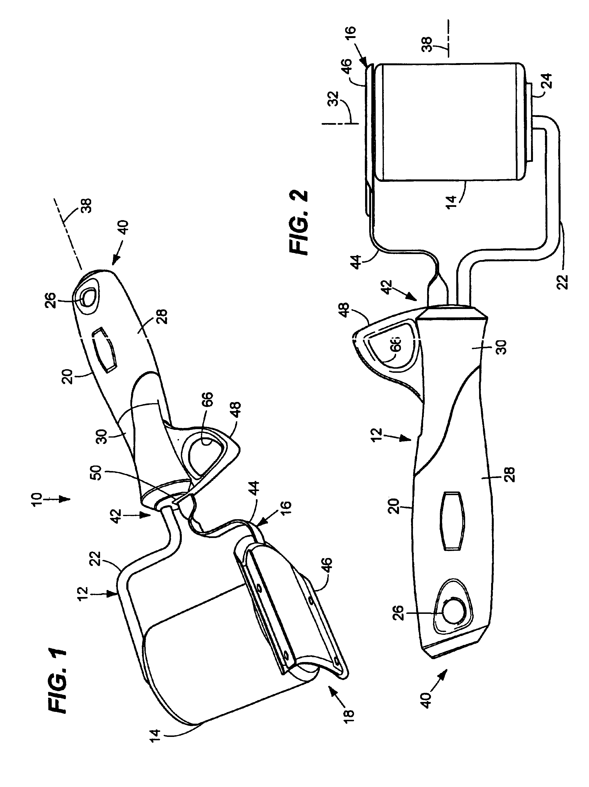
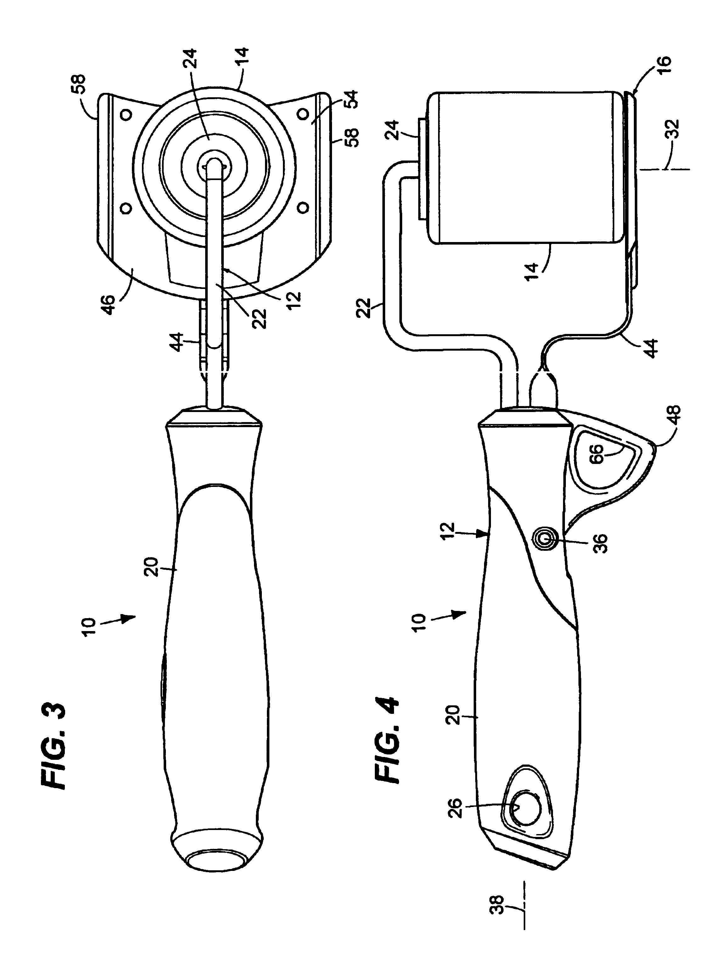
[0035]FIGS. 1-7 illustrate paint applicator 10 (also known as a paint roller tool). Paint applicator 10 generally includes roller support 12, roller 14, and trim system 16. Roller support 12 rotatably supports roller 14 and further supports trim system 16 for movement towards and away from an axial end 18 of roller 14. Roller support 12 generally includes handle 20, frame 22, and bearing member 24 (shown in FIG. 6).

[0036]Handle 20 provides a surface about which a painter may grasp applicator 10. Although handle 20 preferably includes hang hole 26 and an exterior layer 28 of a soft, elastomeric material such as Santroprene® thermoplastic elastomers (Advanced Elastomer Systems, Akron, Ohio) overlying a rigid core 30 of material such as plastic, metal, or wood, handle 20 may omit such features and be made from a variety of other materials. Further, although handle 20 is preferably substantially solid, handle 20 may alternatively include hollow portions to reduce its weight and manufact...


PUM


Abstract

The present disclosure provides a paint applicator which may be used to apply paint to corners, to junctions between adjacent walls, along window trim, along floor moldings, or other surface adjacent to the surface being painted, without smearing paint on the adjacent surface. Moreover, the present disclosure provides a paint applicator having a trim system that prevents the painter's hands from becoming covered with paint upon actuation of trim system.

Description

CROSS REFERENCE TO RELATED APPLICATION[0001]This claims the benefit under 35 U.S.C. §119(e) of U.S. provisional patent application Ser. No. 60 / 342,293, filed Dec. 21, 2001, the disclosure of which, in its entirety, is incorporated herein by reference.FIELD OF THE DISCLOSURE[0002]The present disclosure relates to paint rollers. More specifically, the present disclosure relates to paint rollers having shields or guards for applying paint to surfaces which are adjacent to trim, window moldings, and the like.BACKGROUND OF THE DISCLOSURE[0003]Paint rollers are popular tools for applying paint to large surface areas. Paint rollers typically include a handle, a shaft extending from the handle, and a roller rotatably coupled to the shaft. Although well-suited for applying paint to large expansive areas, such conventional rollers are not well-suited for applying paint to corners, to junctions between adjacent walls, along window trim, or along floor moldings, without smearing paint on the ad...

Claims


Application Information

Patent Timeline
Patent Type & Authority Patents(United States)
IPC IPC(8): B05C17/02B05C21/00
CPCB05C17/02B05C17/0225B05C17/0205
Inventor PRINCE, MICHAEL D.REEDY, MICHAEL H.PATADIA, SONA N.GOULET, MATTHEW G.SERIO, CRAIG S.
Owner NEWELL OPERATING COMPANY
Why Eureka
Try Eureka