Unit connecting mechanism and image display device

a unit connecting mechanism and image display technology, applied in the direction of identification means, electrical apparatus casings/cabinets/drawers, instruments, etc., can solve the problems of inconvenient work that is needed for the unit connecting mechanism of the related art, and achieve the effect of enhancing an increased safety, facilitating and properly performing assembling and disassembling operations

Inactive Publication Date: 2005-08-09
TOSHIBA TRANSPORT ENG
View PDF9 Cites 38 Cited by
  • Summary
  • Abstract
  • Description
  • Claims
  • Application Information

AI Technical Summary

Benefits of technology

[0023]Therefore, it is an object of the present invention to provide an image display device which is able to realize a compact structure that employs a unit connecting mechanism enabled to easily and properly perform assembling and disassembling operations of adjacent display units while enhancing an increased safety for a worker who performs the assembling and disassembling operations.

Problems solved by technology

However, the unit connecting mechanism of the related art suffers from inconvenient work to be needed for a worker to carry out connection or disconnection of the display units by opening the doors of the display units and inserting his hand into a narrow area inside each of the display units to manipulate the connecting members each time the box-like units 1, 1 are assembled or disassembled.
Accordingly, the worker suffers from troublesome and back breaking work and, thus, an improvement over the related art structure is required.

Method used


Image

  • Unit connecting mechanism and image display device
  • Unit connecting mechanism and image display device
  • Unit connecting mechanism and image display device

Examples


first embodiment

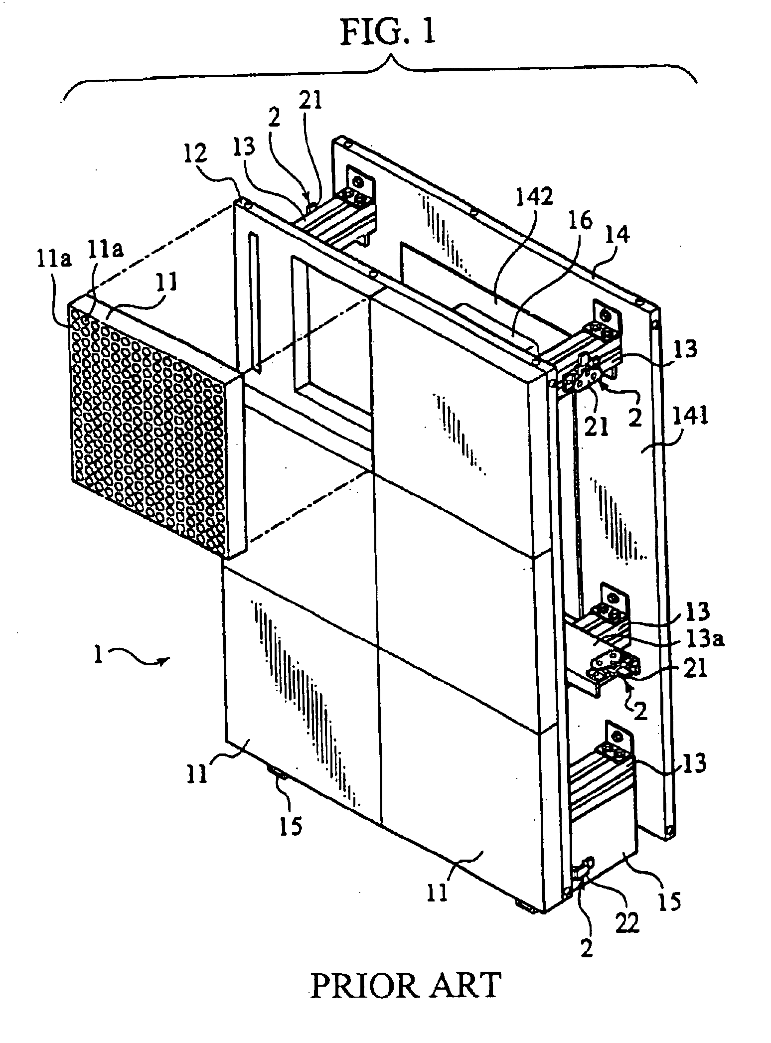
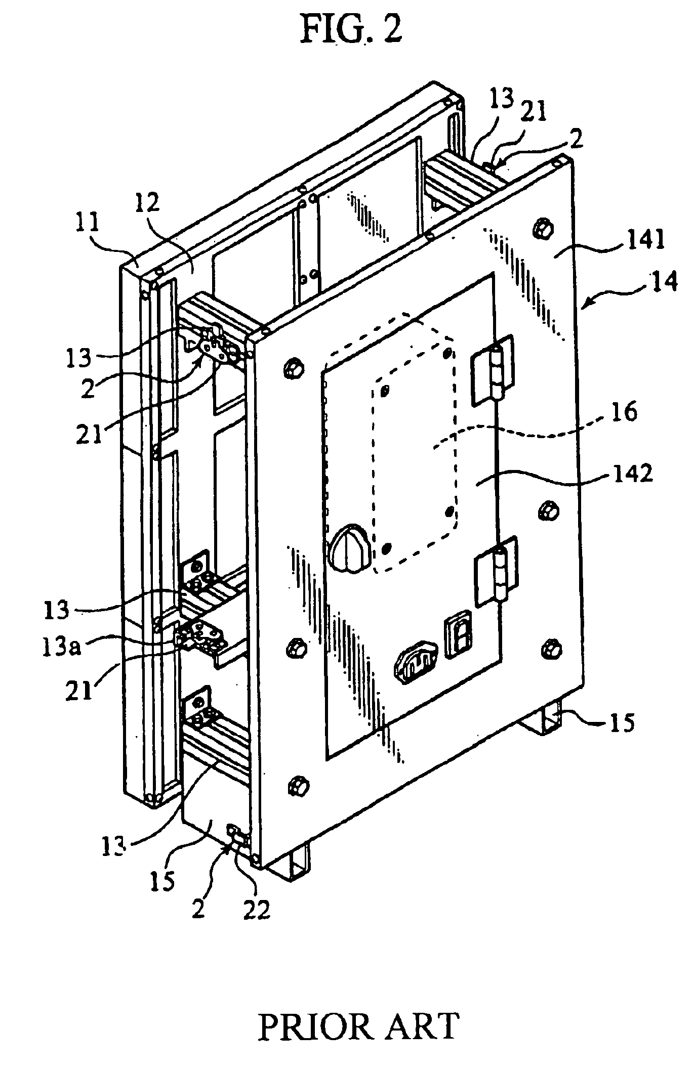
[0049]FIG. 7 is a perspective view of a box-like unit of a first embodiment forming an image display device according to the present invention, and FIG. 8 is a perspective view of the display unit as viewed from a rear side.

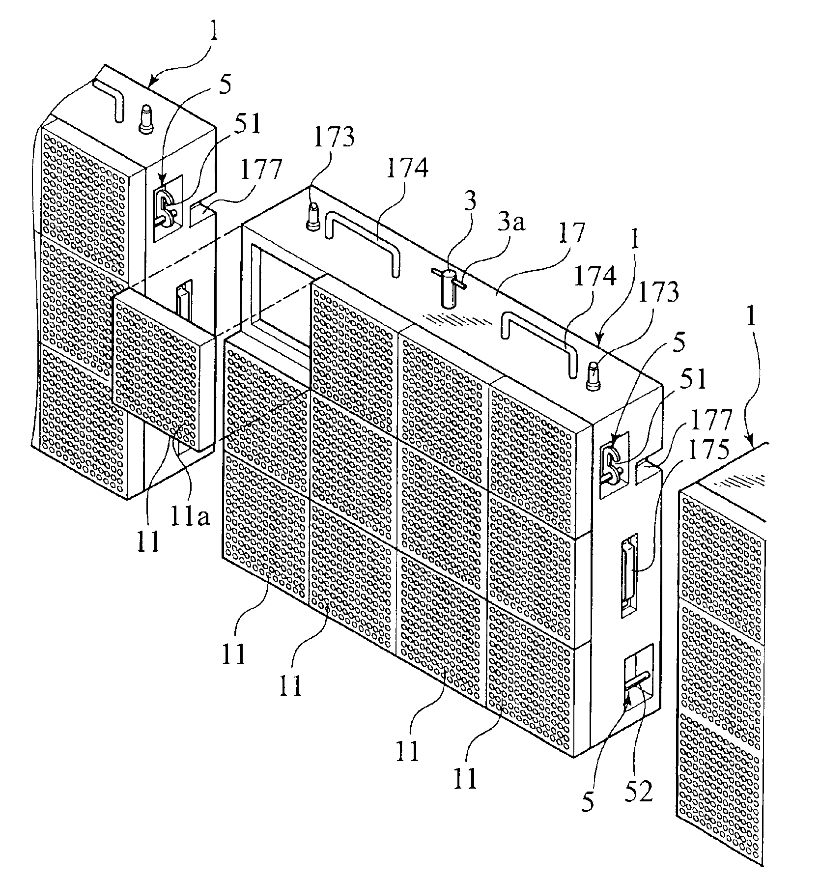
[0050]As shown in FIG. 7, the box-like unit 1 of the embodiment according to the present invention includes a plurality (shown as twelve pieces in this embodiment) of display panels 11, each comprised of a large number of display elements 11a such as LEDs, which are assembled on a flat box-like chassis 17. Also, as shown in FIG. 8, mounted at a rear side of the chassis 17 are double-hinged doors 171, 172, with a control unit 16 being fixedly mounted to an inner wall of the chassis 17 for controlling drive states of the display elements 11a. Also, reference numeral 17a designate grip portions with respective lock mechanisms disposed at the double-hinged doors 171, 172.

[0051]A connecting pin 3 stands upright at a center of an upper surface of the chassis 17 and, li...

second embodiment

[0112]Referring to FIGS. 20A to 21, a connecting mechanism of a second embodiment of the present invention is described. In the second embodiment, the unit connecting mechanism includes an engaging section 700, which serves to fix upper and lower box-like units 1′, 1′ with respect to one another, with a structure different from that of the first embodiment. Accordingly, other parts are substantially the same as those of the first embodiment and, so, like parts bear the same reference numerals as those of the first embodiment to omit redundant description.

[0113]FIG. 19 is a perspective view of a box-like unit 1′ of the second embodiment as viewed from a rear side thereof.

[0114]Also, FIGS. 20A, 20B and 21 are views illustrating how an engaging rod 3a of a connecting pin 3 is caught with an associated engaging member 777.

[0115]That is, as shown in FIG. 20A, prior to catching the engaging rod 3a with the engaging member 777, the upper box-like unit 1′ is stacked in such a way to be posi...


PUM


Abstract

A unit connecting mechanism and box-like unit is disclosed having an engaging unit (4) and a connecting pin (3) which are mounted to the box-like unit (1) to allow a plurality of box-like units (1,1) to be coupled to one another in a vertical direction. A handle (44) is operatively connected to a hook (43) to catch an engaging rod (3a) and is vertically raised to cause a stopper (45) to lock the hook (43) and the engaging rod (3a) in a locked condition, with operation of the handle (44) causing the stopper (45) to move downward to cause the hook disengage from the engaging rod for thereby uncoupling the box-like units (1,1) from one another. As a result, the unit connecting mechanism can be manufactured in a compact structure, providing a capability for a worker to easily and appropriately perform coupling and uncoupling operations of the box-like units.

Description

BACKGROUND OF THE INVENTION[0001]1. Field of the Invention[0002]The present invention relates to LED display devices and, more particularly, to an image display device with a structure in which a plurality of display units, each comprised of a display panel, are arrayed in a vertical or lateral direction to provide an image in an enlarged scale, and an improvement over a unit connecting mechanism suited for connecting the plural display units to form the image display device.[0003]2. Description of the Related Art[0004]Image display devices of a large screen each including a display panel composed of a large number of display elements, such as LEDs (Light Emitting Diodes), which are disposed in a matrix form are mounted on outer walls (building boards) of buildings located in indoor or outdoor gymnasiums, a variety of event sites or business quarters. These image display devices are structured to be operative to provide displays of advertisements or guidance, or displays of televisi...

Claims


Application Information

Patent Timeline
Patent Type & Authority Patents(United States)
IPC IPC(8): G09F9/00H05K5/00
CPCG09F9/00G09F9/33H05K5/0021G09F9/3026
Inventor NAGAMINE, ATSUSHIENDO, YUJISODENO, ETSUO
Owner TOSHIBA TRANSPORT ENG
Why Eureka
Try Eureka