Tide compensated swell powered generator

a generator and swell technology, applied in the direction of electric generator control, electric motor propulsion transmission, locomotive transmission, etc., can solve the problems of loss of efficiency, difficulty in coordinating electrical output with demand, and variability in the range of motion of the float riding on the swell, so as to minimize the friction inherent in the rise and fall of each float, reduce the friction, and minimize the effect of friction

Inactive Publication Date: 2005-08-16
MONTGOMERY W C GRAY
View PDF23 Cites 47 Cited by
  • Summary
  • Abstract
  • Description
  • Claims
  • Application Information

AI Technical Summary

Benefits of technology

[0010]It is another object of the invention to minimize the friction opposing the rise and fall of the float.
[0016]Each float also rises and falls along a guide rod. The friction inherent in the rise and fall of each float is minimized by positioning two columns of opposing magnets, one on the guide rod and the other on the part of the float mounted to the guide rods. The force of the magnets opposing each other will minimize the contact between the float and the guide rod, thereby minimizing the friction. Friction is also reduced by providing a plurality of nozzles which are configured to spray water between the float and the guide rod.

Problems solved by technology

Such systems typically require the existence of a natural constricted inlet, and thus are only applicable to only a limited coastal environment.
This will cause the turbines to generate maximum amounts of electricity at different times each day, making it difficult to coordinate electrical output with demand.
If the electricity is not to be used there, lines must be laid to carry the electricity inland, which can lead to a loss of efficiency.
As the float falls with a falling swell, it will pull air through the turbine, causing it to turn.
One problem that arises with any swell driven system is that the range of motion of the float riding on the swells will vary with the size of the swells and with the level of the sea in view of the tide.
Another problem that such systems face is friction opposing the rise and fall of the float.
This friction will reduce the motion of the float and ultimately reduce the electric output of the system.
This can cause the flow of water to the turbine to be intermittent.

Method used


Image

  • Tide compensated swell powered generator
  • Tide compensated swell powered generator
  • Tide compensated swell powered generator

Examples


Embodiment Construction

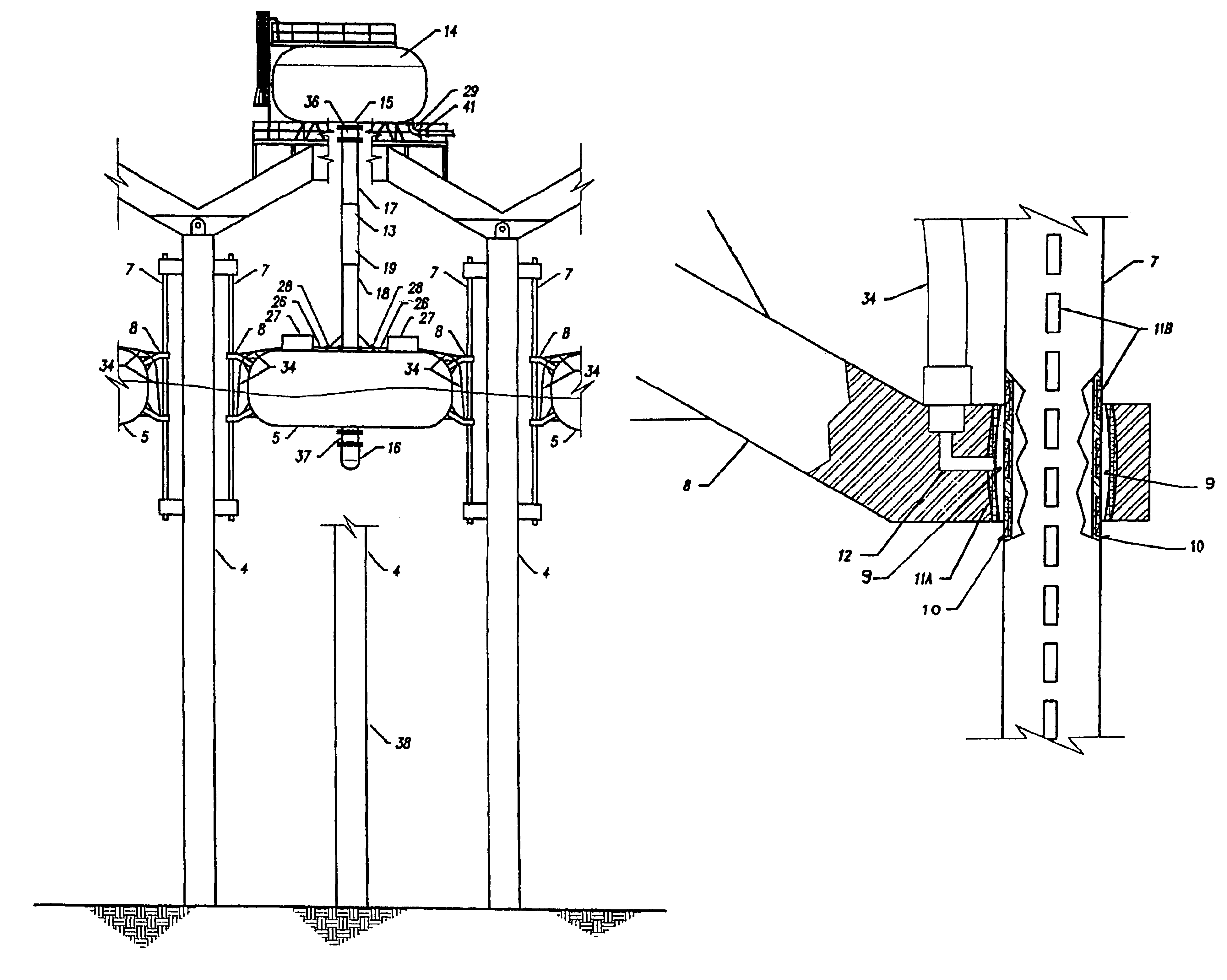
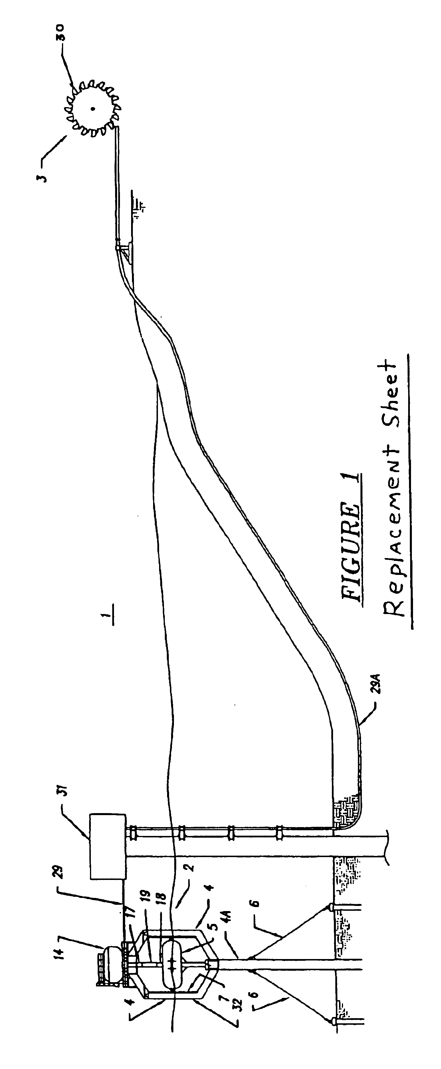
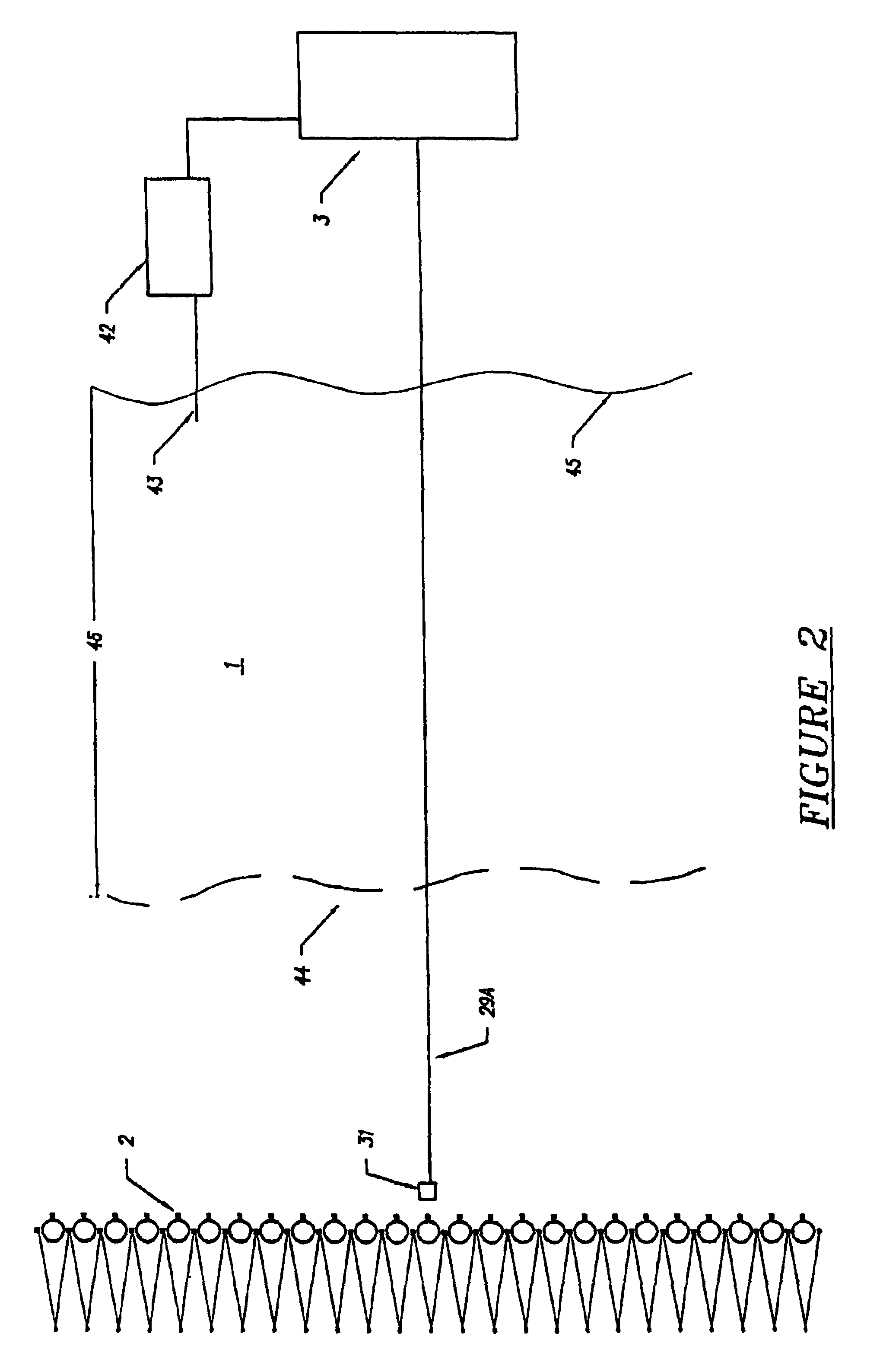
[0034]The invention is a swell powered generator system 1. It is designed to convert the energy of swells in the open ocean, defined for purposes of this invention as that body of water outside the breaker line, into electricity. The system 1 is comprised of two principal components, a float system 2 and a generator system 3.

[0035]Float system 2 is comprised of float frame 32, preferably comprising a plurality of float guide legs 4, most preferably three ft. by three ft. box beams. In the preferred embodiment, there are three such legs 4 per float 5. In one embodiment, each leg 4 extends vertically from the ocean floor, thereby comprising a support structure 33. However, in another embodiment, legs 4 merge into a single leg 4A below float 5. In this embodiment, only single leg 4A will extend to the ocean floor. Single leg 4A will be anchored to the ocean floor with a plurality of cables 6, preferably four per leg. Legs 4 and 4A as well as the rest of float system 2 should preferably...


PUM


Abstract

The invention comprises a float system having a float connected to a pump line and a reservoir tank. As the float rises and falls with the passing swells, it forces water through the pump line into a reservoir tank. An outflow line connects the reservoir line to a generator system, preferably located on shore, where the flowing water is used to drive a turbine and generate electricity. Preferably, there are a plurality of reservoir tanks, each with its own float and pump line, delivering water to the generator system. The flow of water through the pump line is kept steady by providing each reservoir tank with a pressurized air cushion which provides for constant outflow of water from each tank despite variances in the inflow.

Description

FIELD OF THE INVENTION[0001]The invention relates to swell driven generators in general and to pump type swell powered generators in particular.PRIOR ART[0002]There have been many attempts to harness the mechanical power of the ocean to create electricity. Examples include generators that harness the inflow and outflow of water into constricted inlets at the shore. Turbines are placed in the constricted inlet, and the force of the water moving through it drives the turbines to generate electricity. Such systems typically require the existence of a natural constricted inlet, and thus are only applicable to only a limited coastal environment. Additionally, such systems depend upon tidal movement for water flow to drive the turbines. The amount of water displaced by tidal movement will vary with lunar phase, which will affect the total amount of electricity such systems can generate. Likewise, the time of maximum tidal movement will change from day to day depending upon the lunar phase...

Claims


Application Information

Patent Timeline
Patent Type & Authority Patents(United States)
IPC IPC(8): F03B13/18F03B13/26F03B13/00
CPCF03B13/1845F03B13/26Y02E10/28Y02E10/38Y02E10/30Y02E10/20
Inventor MONTGOMERY, W. C. GRAY
Owner MONTGOMERY W C GRAY
Why Eureka
Try Eureka