
High speed cooking oven having an air impingement heater with an improved orifice configuration

Active Publication Date: 2005-08-23
LINCOLN FOODSERVICE PRODS
View PDF13 Cites 46 Cited by
  • Summary
  • Abstract
  • Description
  • Claims
  • Application Information

AI Technical Summary

Problems solved by technology

Although effective, this round air slot shape limits the cooking of the food and also limits heat transfer on to the surface of the food.
Although effective in cooking and / or toasting an outer surface of the food a detriment is that an inner surface of the food can potentially remain raw or relatively less cooked than desired due to this sweeping of the air stream across the food.

Method used


Image

  • High speed cooking oven having an air impingement heater with an improved orifice configuration
  • High speed cooking oven having an air impingement heater with an improved orifice configuration
  • High speed cooking oven having an air impingement heater with an improved orifice configuration

Examples


Embodiment Construction

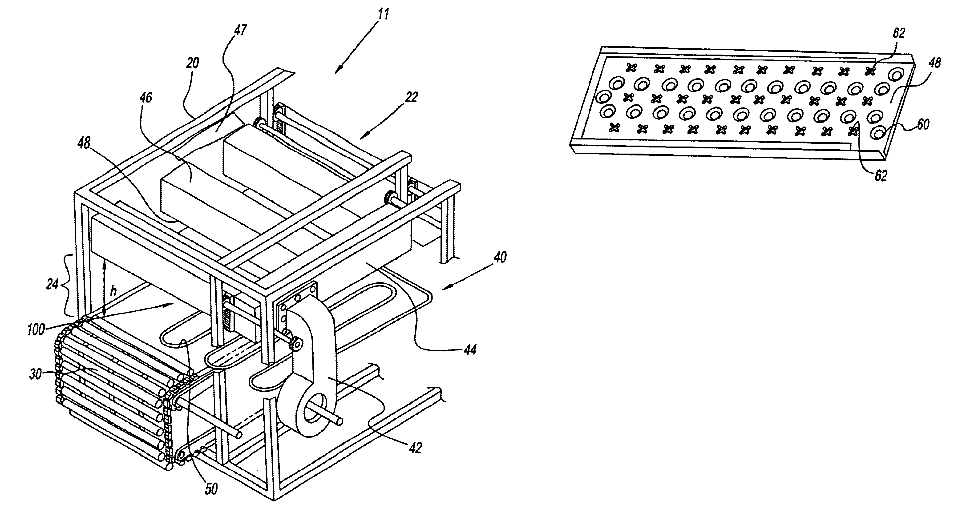
[0039]With reference to FIGS. 1 through 13, there is provided a high speed cooking device 11. The high speed cooking device 11 has a housing 20, a conveyer belt assembly 30, and an air impingement assembly 40. Additionally, a heater 50 may be employed with the high speed cooking device 11.

[0040]The housing 20 has an inlet point 22 and an outlet point 24. A raw food product enters the high speed cooking device 11 by the inlet point 22 and traverses by the conveyer belt assembly 30 to the outlet point 24 where the food emerges being cooked.

[0041]The air impingement assembly 40 is located preferably immediately above the conveyor belt assembly 30 as shown in FIG. 1. The conveyor belt assembly 30 and the air impingement assembly 40 are separated by a height, h. A cooking passageway is located in height h. Optionally, the heater 50, when used with the improved orifice configuration is located immediately below the conveyor belt assembly 30, and / or above the cooking passageway 100. The he...


PUM


Abstract

An air impingement oven having a conveyor belt assembly for moving food through a heat treatment passage. The air impingement oven has a fan, a supply duct, a plenum and a number of jet fingers being disposed above the conveyor belt assembly. The jet fingers have a base portion having a number of orifices for directing the impingement air onto the food. The orifices have an improved configuration. The improved configuration intensifies the airflow on the food to penetrate heat into the food surface thereby improving heat transfer. The improved configuration reduces a cooking time of the food in the air impingement oven.

Description

CROSS REFERENCE TO RELATED PATENT APPLICATIONS[0001]This application under 35 U.S.C. § 119 hereby claims priority to U.S. Provisional Patent Application No. 60 / 477,421 filed on Jun. 10, 2003, the entire contents of which is hereby incorporated by reference in its entirety.FIELD OF THE INVENTION[0002]This invention relates to a high speed cooking oven used in commercial cooking. More particularly, the present invention relates to a cooking device that is capable of rapidly cooking food using an air impingement heater having an improved orifice configuration.BACKGROUND OF THE INVENTION[0003]Ovens such as tunnel ovens for cooking bread products are known in the art. Tunnel ovens use air impingement heaters. The air impingement heaters are used in toasting / cooking bread products such as pizza, toast and the like. One example of such a tunnel oven is shown in U.S. Pat. No. 4,873,107 to Archer. Archer discloses a tunnel oven. The tunnel oven has a conveyor belt for moving food through a h...

Claims


Application Information

Patent Timeline
IPC IPC(8): A21B1/00A21B1/26F27B9/00F27D11/00F27B9/10A21B1/24A21B1/48A23L1/00A47J37/04
CPCA21B1/245A21B1/48A47J37/044
Inventor HENKE, MITCHELL C.NEALLEY, CAROL S.
Owner LINCOLN FOODSERVICE PRODS
Features
  • Generate Ideas
  • Intellectual Property
  • Life Sciences
  • Materials
  • Tech Scout
  • Unparalleled Data Quality
  • Higher Quality Content
  • 60% Fewer Hallucinations
Learn More