Frequency synthesizing circuit having a frequency multiplier for an output PLL reference signal

a frequency multiplier and reference signal technology, applied in the field of frequency synthesizing circuits, can solve the problems of accumulating an extremely large amount of phase errors, vco's higher phase noise, and the prior art described above still has some defects, so as to achieve the effect of minimizing phase error accumulation

Inactive Publication Date: 2005-08-23
NAT CENT UNIV
View PDF4 Cites 14 Cited by
  • Summary
  • Abstract
  • Description
  • Claims
  • Application Information

AI Technical Summary

Benefits of technology

[0008]An object of the present invention is to provide a frequency synthesizing circuit which achieves double frequency multiplication by means of a phase-locked loop incorporated with a delay-locked loop so as to minimize phase error accumulations.
[0010]For achieving the purposes described above, the frequency synthesizer according to the present invention includes a frequency multiplier and a phase-locked loop, wherein the frequency multiplier converts a low frequency reference signal into a high frequency signal for being a reference signal to the phase-locked loop, so that the loop bandwidth of the phase-locked loop can be increased to reduce output jitter.
[0011]Here, the frequency multiplier consists of a delayed locked loop and a phase synthesizer. The delay-locked loop is utilized to generate multi-phase output signals that equivalently divides a cycle of the reference signal. And the multiplication of reference signal is accomplished by synthesizing different output phases of the delay-locked loop, which is controlled by the coefficient of the frequency multiplier. Through double frequency multiplication achieved by the delay-locked loop incorporated with the phase locked loop, the accumulated phase error can be reduced compared to that in a conventional phase-locked loop due to a wider loop bandwidth can be applied. Herein, frequency multiplied can be accomplished by adjusting the coefficients of frequency multiplier or the divider of the phase-locked loop.

Problems solved by technology

But it often accumulates an extremely large amount of phase errors.
In addition, for a low frequency reference signal, the PLL loop bandwidth should be narrowed down which may result in higher phase noise introduced by VCO.
Thus it can be seen, the prior art described above still has some defects, is not a good design, however, and is urgently to be improved.

Method used


Image

  • Frequency synthesizing circuit having a frequency multiplier for an output PLL reference signal
  • Frequency synthesizing circuit having a frequency multiplier for an output PLL reference signal
  • Frequency synthesizing circuit having a frequency multiplier for an output PLL reference signal

Examples


Embodiment Construction

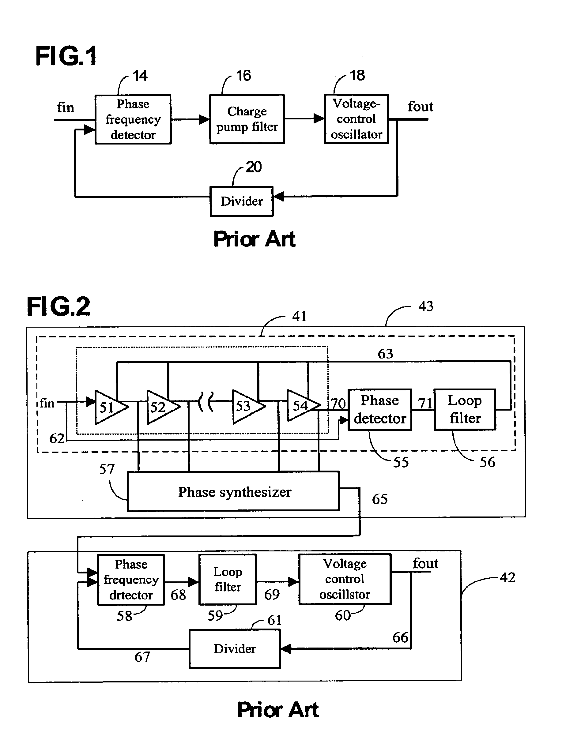
[0021]Please refer to FIG. 2, which illustrates a frequency synthesizing circuit according to the present invention. The frequency synthesizing circuit mainly includes a frequency multiplier 43 and a phase-locked loop 42, wherein the frequency multiplier 43 converts a low frequency reference input signal fin 62 into a high frequency output 65 for being provided as a reference to the phase-locked loop 42. A phase frequency detector (PFD) 58 compares the reference signal 65 with an output signal 67 to obtain phase and frequency difference and generates a modulated signal 68. Then, the modulated signal 68 is converted into a substantial DC voltage 69 by a loop filter 59 for further modulating a frequency of a voltage control oscillator 60.

[0022]An output signal 66 of the voltage controlled oscillator 60 can be downconverted by a divider 61, wherein the downconverted signal 67 outputted by a divider is connected to the phase frequency detector 58.

[0023]The frequency multiplier 43 accord...


PUM


Abstract

A frequency synthesizing circuit is provided. The frequency synthesizing circuit includes a frequency multiplying circuit and a phase-locked loop, wherein the frequency multiplying circuit can converts a reference signal having a low frequency into a high frequency signal for being a reference signal of the phase-locked loop, so that the loop bandwidth of the phase-locked loop can be increased to reduce jitter of the output signal. The present invention utilizes the delay-locked loop to generate multiphase output signals that equivalently divide a cycle of the reference signal for achieving a frequency multiplying through cooperating with a phase synthesizer. Through double frequency multiplying functions of the delay loop and the phase locked loop, a phase error accumulation caused by the single frequency multiplying of the conventional phase-locked loop with narrow loop bandwidth can be reduced. Furthermore, the frequency multiplying can be adjusted by synthesizing different phases of delay-locked loop and the divider coefficient of the phase-locked loop.

Description

BACKGROUND OF THE INVENTION[0001]1. Field of the Invention[0002]The present invention relates to a frequency synthesizing circuit, and particularly to a frequency synthesizer which has a low frequency reference signal, a high frequency output, and a high multiple for frequency synthesizing.[0003]2. Description of the Prior Art[0004]Phase-Locked Loop (PLL) is a technique usually used in a frequency synthesizing circuit, as shown in FIG. 1. The basic framework thereof includes a phase-frequency detector (PFD) 14, a charge pump loop filter (CPF) 16, a voltage control oscillator (VCO) 18 and a divider 20. Through the function of the PFD, the output frequency of the VCO can be adjusted accordingly. When the loop is phase locked, the output frequency (fvco) of the VCO and the frequency (fref) of the reference signal will satisfy the formula of fvco=N×fref, wherein N is a coefficient of the divider.[0005]For an application of a high frequency generator (>100 MHz) with a low reference fr...

Claims


Application Information

Patent Timeline
Patent Type & Authority Patents(United States)
IPC IPC(8): H03B21/02H03B21/00H03L7/07H03L7/081H03L7/18
CPCH03B21/02H03L7/07H03L7/0812H03L7/18H03L7/0816
Inventor CHEN, WEI-ZEN
Owner NAT CENT UNIV
Why Eureka
Try Eureka