
Reinforced payload container

a payload container and reinforcement technology, applied in the field of payload containers, can solve the problems of metal sag or quickly wear out, and the amount of payload that may be hauled in an off-highway truck is often limited,

Inactive Publication Date: 2005-08-30
CATERPILLAR INC
View PDF13 Cites 33 Cited by
  • Summary
  • Abstract
  • Description
  • Claims
  • Application Information

AI Technical Summary

Benefits of technology

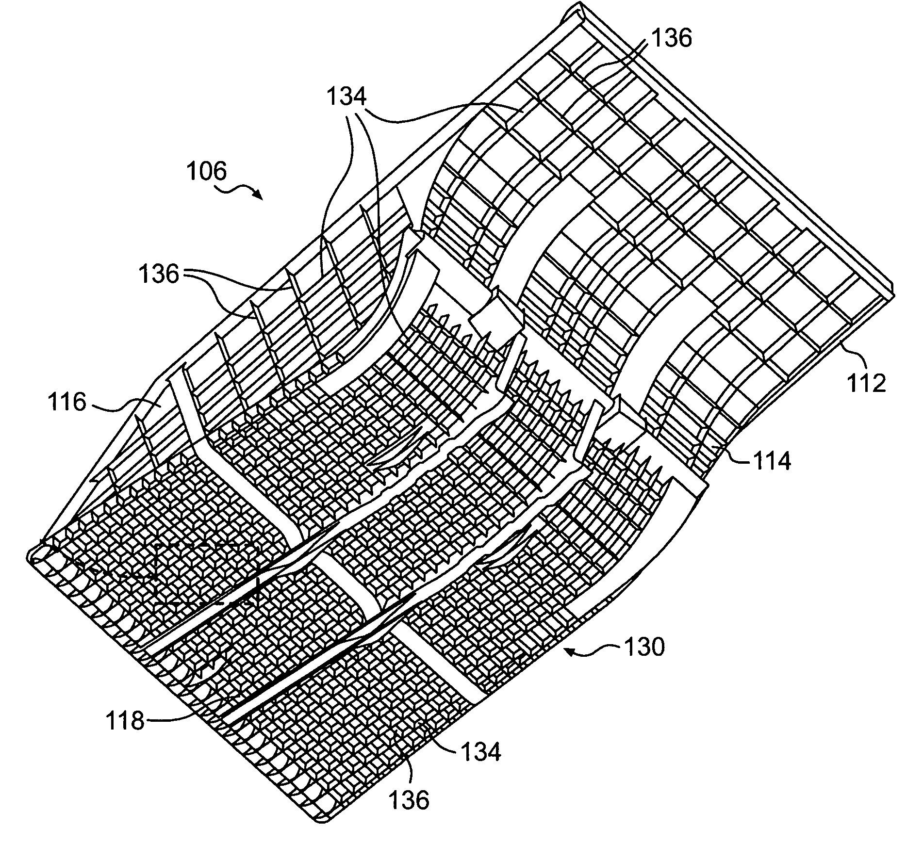
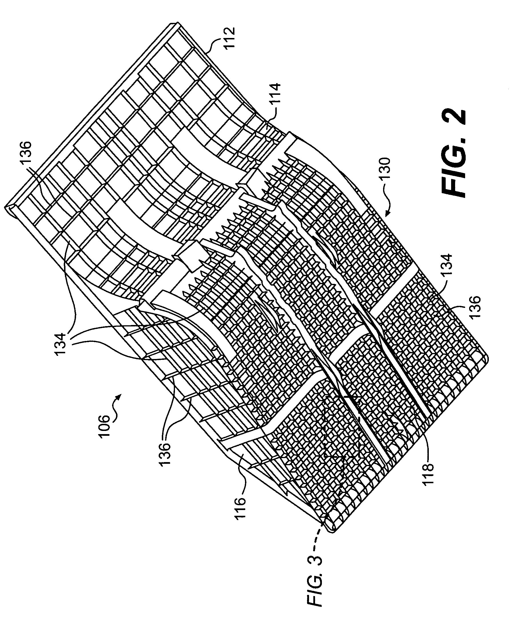
[0006]One aspect of the present disclosure is directed to a reinforced payload container. The payload container may include a panel forming at least one of a floor, a sidewall, and a front wall. A first plurality of ribs may be attached to the panel, and may include a first free edge and a first panel edge. A second plurality of ribs may also be attached to the panel and may intersect with the first plurality of ribs. The second plurality of ribs may include a second free edge and a second panel edge. The first plurality of ribs may include first rib slots along the first free edge, and the second plurality of ribs may include second rib slots along the second panel edge. The first rib slots and the second rib slots may be aligned so that the first rib slots receive the second ribs and the second rib slots receive the first ribs.
[0007]In another aspect, the present disclosure is directed to a reinforced payload container having a panel forming at least one of a floor, a sidewall, and a front wall. A first plurality of ribs may have a first free edge and a first panel edge, and may be

Problems solved by technology

The amount of a payload that may be hauled in an off-highway truck is often limited by the requirement that the combined weight of the payload and truck not exceed an established maximum gross vehicular weight (GVW).
However, as the amount of metal utilized in the off-highway truck is decreased, the durability and life of the truck may be negatively affected.
For example, the use of thin metal in a payload container can cause the metal to sag or to wear out quickly.
Accordingly, there is an undesirable chance of deformation of the metal.

Method used


Image

  • Reinforced payload container
  • Reinforced payload container
  • Reinforced payload container

Examples


Embodiment Construction

[0014]Reference will now be made in detail to exemplary embodiments that are illustrated in the accompanying drawings. Wherever possible, the same reference numbers will be used throughout the drawings to refer to the same or like parts.

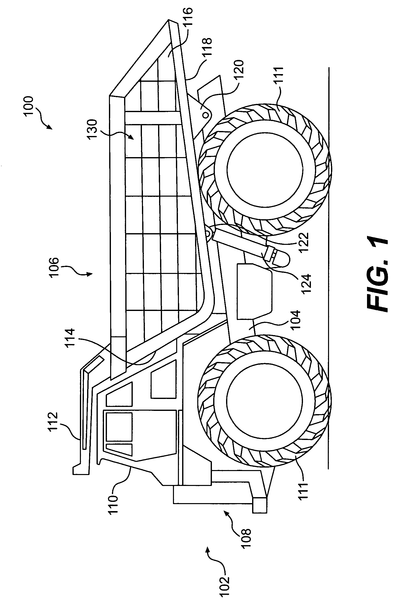
[0015]An exemplary embodiment of a work machine 100 is illustrated in FIG. 1. The work machine 100 may be an off-highway truck, as shown, or other vehicle, such as an articulated truck, an off-highway tractor, or other work-machine. The exemplary work machine 100 may include a front end 102, a frame 104, and a payload container 106. The front end 102 may include an engine compartment 108 and an operator's cab 110. The engine compartment 108 may house an engine, a transmission, and / or other components used to power the work machine 100. The operator's cab 110 may include controls for operating and driving the work machine 100. The engine in the engine compartment 108 drives wheels 111 attached to the frame 104, in a manner known in the art.

[0016]The p...


PUM


Abstract

A reinforced payload container may include a panel forming at least one of a floor, a sidewall, and a front wall. A first plurality of ribs may be attached to the panel and may include a first free edge and a first panel edge. A second plurality of ribs may also be attached to the panel and may intersect with the first plurality of ribs. The second plurality of ribs may include a second free edge and a second panel edge. The first plurality of ribs may include first rib slots along the first free edge, and the second plurality of ribs may include second rib slots along the second panel edge. The first rib slots and the second rib slots may be aligned so that the first rib slots receive the second ribs and the second rib slots receive the first ribs.

Description

TECHNICAL FIELD[0001]This disclosure is directed to a payload container and, more particularly, to a support structure for the payload container.BACKGROUND[0002]The amount of a payload that may be hauled in an off-highway truck is often limited by the requirement that the combined weight of the payload and truck not exceed an established maximum gross vehicular weight (GVW). The maximum GVW is a limit established based on such things as the power-train and the weight that can be carried by tires. Because off-highway trucks are manufactured from metals in order to be durable and robust, the trucks also are heavy. Any reduction in the truck's weight allows an operator to increase the payload weight by the same amount without exceeding the maximum GVW. To the operator, any increase in payload translates to an increase in productivity, resulting in higher profits. Further, a reduction of the weight of the truck lowers operating costs by reducing fuel consumption when the truck is not lo...

Claims


Application Information

Patent Timeline
IPC IPC(8): B62D33/02B60P1/28
CPCB60P1/286B62D33/02
Inventor LABAN, CHRISTOPHER SCOTTDAHL, KRISTOFOR LEECOINS, TERRY ALLENORMISTON, EDWARD PATRICKMILLER, CLIFFORD EUGENECUSACK, CHRISTOPHER CHARLESBROMENSHENKEL, TIMOTHY JAMESFENNELL, THOMAS EDMUNDBUSHONG, STEPHANFRANKLIN, HOWARD ROY
Owner CATERPILLAR INC
Learn More