Two-way retainer for a slide track assembly of drawers

a technology of slide track and assembly, which is applied in the direction of drawers, furniture parts, domestic applications, etc., can solve the problems of inconvenient use for users of slide track operation, and achieve the effect of increasing useful convenien

Inactive Publication Date: 2005-08-30
KING SLIDE WORKS CO LTD
View PDF5 Cites 84 Cited by
  • Summary
  • Abstract
  • Description
  • Claims
  • Application Information

AI Technical Summary

Benefits of technology

[0008]The primary objective of this invention is to provide a two-way retainer for a slide track assembly of drawers, which comprises a retaining mechanism mounted on a first slide track, and a stop member mounted on a second slide track. The retaining mechanism is consisted of a pair of retaining arms, and each of the retaining arms is formed with an inclined portion and an engaging portion for selectively engaging or disengaging with or from the stop member, thereby increasing useful convenience.

Problems solved by technology

Therefore, it is inconvenient to users for operating the slide tracks in use.

Method used


Image

  • Two-way retainer for a slide track assembly of drawers
  • Two-way retainer for a slide track assembly of drawers
  • Two-way retainer for a slide track assembly of drawers

Examples


first embodiment

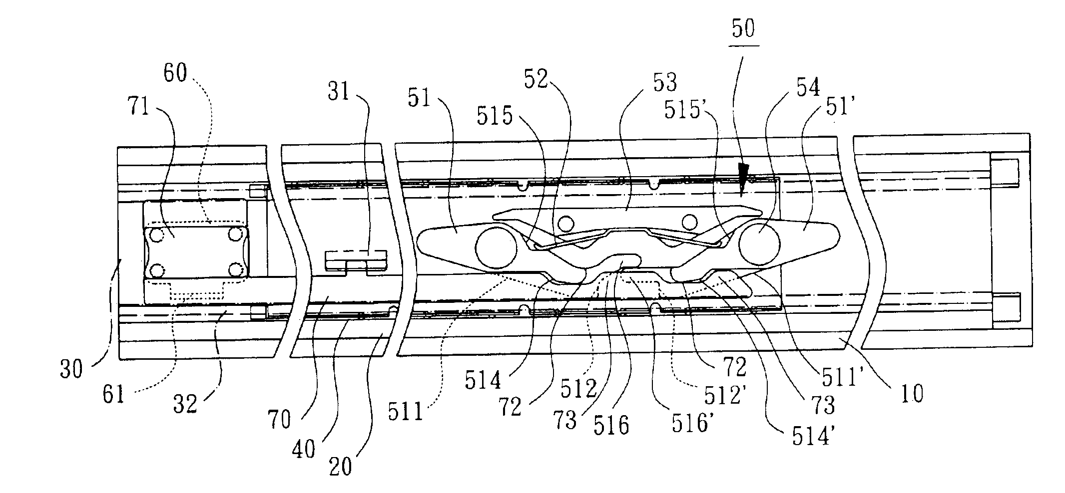
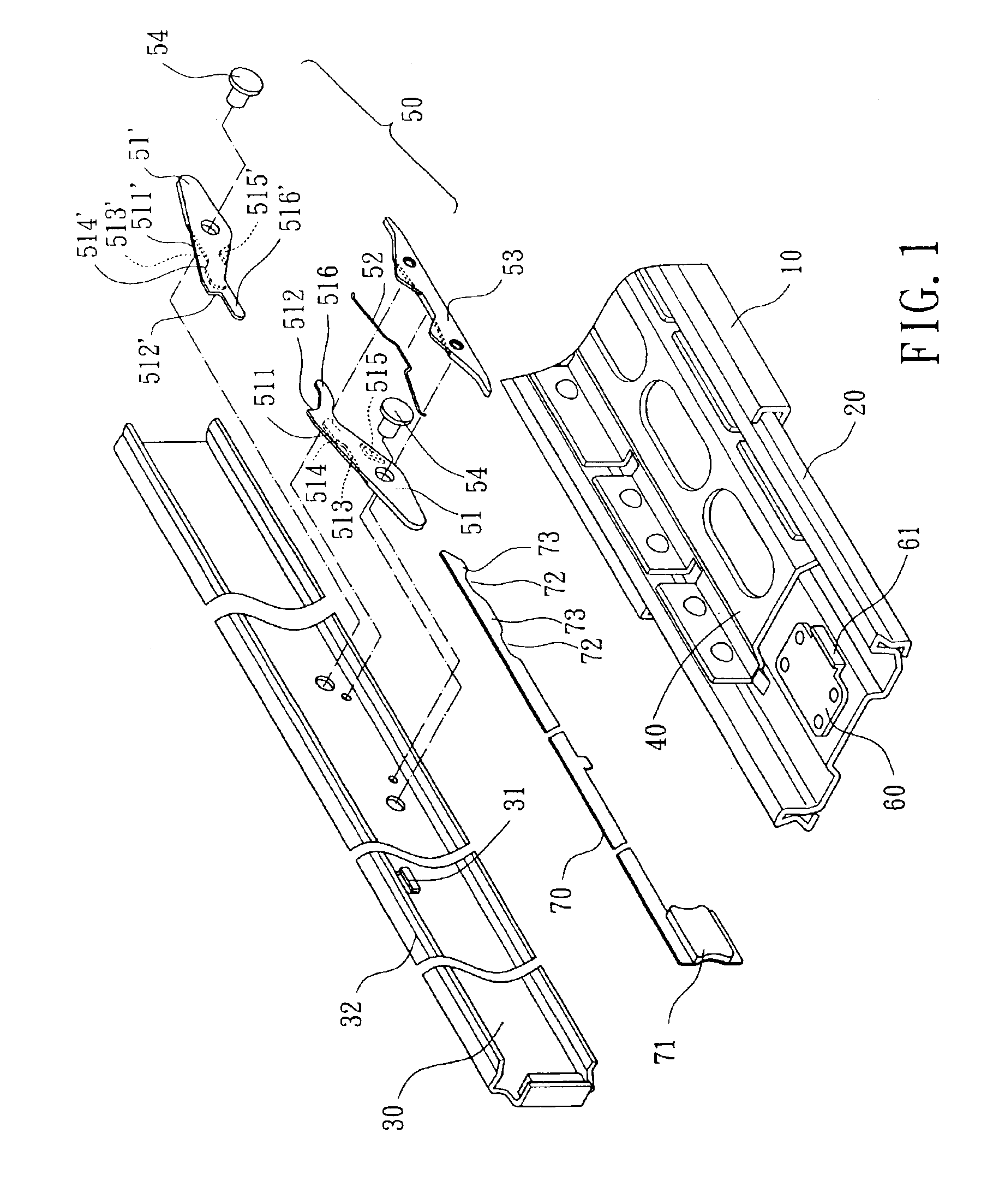
[0027]Referring to FIGS. 1 through 3, a two-way retainer for a slide track assembly of drawers in accordance with the present invention comprises a retaining mechanism 50, a stop member 60 and an unlatching member 70. The retaining mechanism 50 and the unlatching member 70 are mounted at an appropriate position of an inner side of the first slide track 30 while the stop member60 mounting to an end of the second slide track 20. Ball tracks 40 are sandwiched in between any two of the first slide track 30, the second slide track 20 and the third slide track 10.

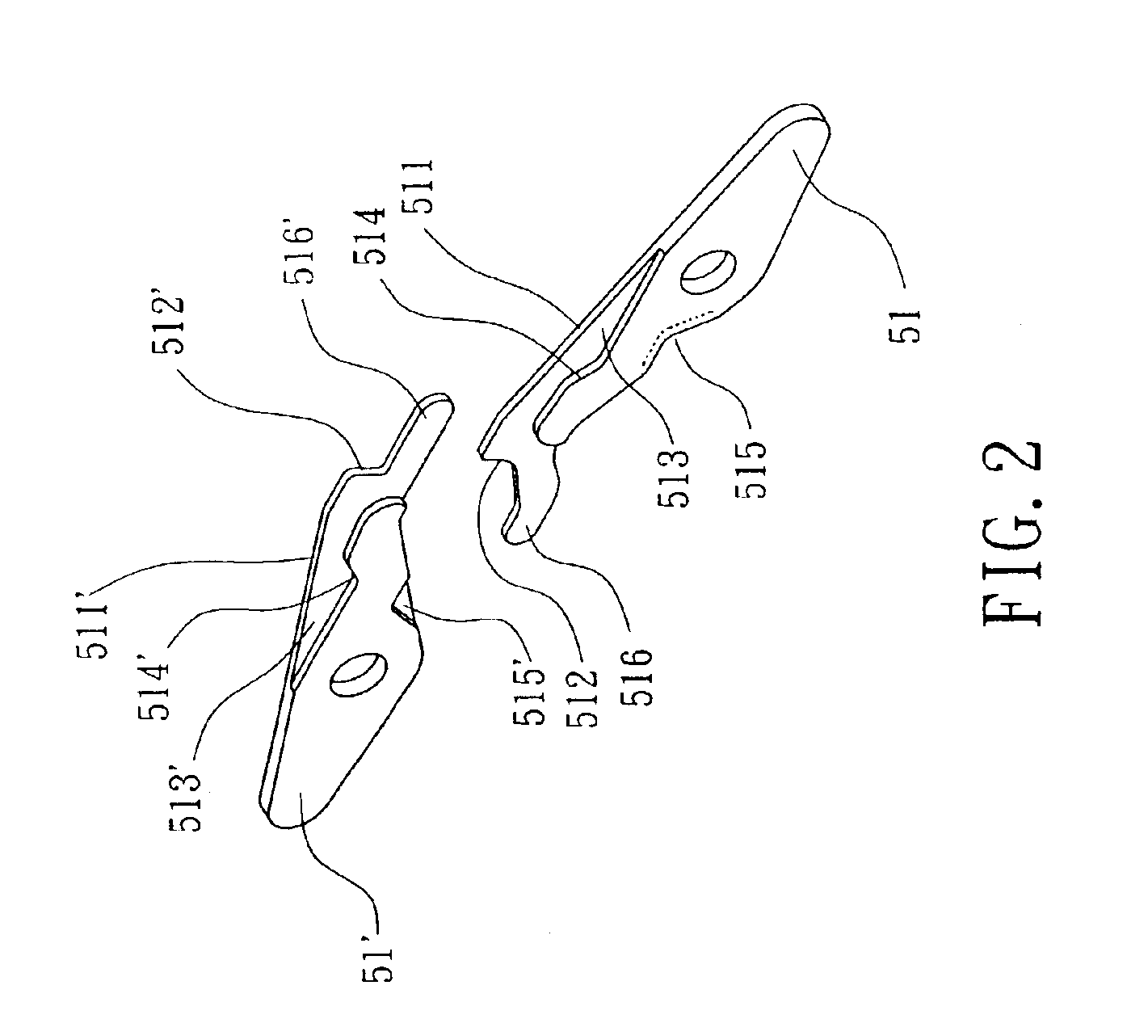
[0028]Referring again to FIGS. 1 through 3, the retaining mechanism 50 comprises a pair of retaining arms 51, 51′, an elastic member 52, a base 53 and a pivotal member 54. Each of the retaining arms 51, 51′ includes an inclined portion 511, 511′, a first engaging portion 512, 512′, a step portion 513, 513′, a second engaging portion 514, 514′ and a recession 515, 515′. The elastic member 52 is adapted to bias the retaining arms 5...

second embodiment

[0038]Referring to FIG. 7, a two-way retainer for a slide track assembly of drawers in accordance with the present invention further includes an unlatching member 70 and a holder 80 adapted to hold a rod body of the unlatching member 70. To accomplish reciprocating operation, the unlatching member 70 is provided with at least one lug 74 and engaged with an elastic member 81 of the holder 80.

[0039]In another design choice, an end of the unlatching member 70 is mechanically connected to an end of the retaining arm 51′ which is oppose to the first engaging portion 512′ (shown at “circle a” in FIG. 7). In unlatching operation, the retaining arm 51′ may be pivoted on the pivotal member 54 by the unlatching member 70, and an engaged relationship of the retaining arm 51′ may actuate the other retaining arm 51 synchronously. Then the retaining arms 51, 51′ are disengaged from the stop member 60 that accomplishes the same unlatching function.

[0040]In another design choice, the retaining memb...


PUM


Abstract

A two-way retainer for a slide track assembly comprises a retaining mechanism mounted on a first slide track, and a stop member mounted on a second slide track. The retaining mechanism is consisted of a pair of retaining arms and an elastic member. The retaining arms are provided with a pair of oppositely inclined portions and a pair of engaging portions. The stop member is provided with a protrusion adapted to interact with the oppositely inclined portions and the engaging portions of the retaining arms. When the first slide track is moved to a predetermined position with respect to the second slide track, the protrusion of the stop member may pass through one of the inclined portions of the retaining arms. Thus the protrusion is confined within the two engaging portions of the retaining arms to thereby retain the first slide track in a two-way direction of the second slide track.

Description

BACKGROUND OF THE INVENTION[0001]1. Field of the Invention[0002]The present invention is related to a two-way retainer for a slide track assembly of drawers. More particularly, the present invention is related to a retaining mechanism mounted on a first slide track, and a stop member mounted on a second slide track adapted to retain the first slide track in a two-way direction.[0003]2. Description of the Related Art[0004]Referring to FIG. 14, a conventional three-section slide track for a drawer includes a first slide track (so-called outer slide track) 30, a second slide track (so-called medium track) 20 and a third slide track (so-called inner track) 10. A ball track 40 is sandwiched in between any two of the first slide track 30, the second slide track 20 and the third slide track 10 so as to smoothen sliding movement. Moreover, the first slide track 30 and the second slide track 20 mount a retaining member 301 and a stop member 201 respectively for retaining in a one-way directi...

Claims


Application Information

Patent Timeline
Patent Type & Authority Patents(United States)
IPC IPC(8): A47B88/04A47B88/14
CPCA47B88/14A47B2088/0403A47B2210/0018A47B2210/0059A47B88/53A47B88/57A47B88/403A47B88/487A47B88/50
Inventor CHEN, KEN-CHINGHWANG, SHIH-LONGWANG, CHUN-CHIANG
Owner KING SLIDE WORKS CO LTD
Why Eureka
Try Eureka