Diagnosis oriented lossy compression of medical images

a lossy compression and medical image technology, applied in the field of teleradiology, can solve the problems of reducing or even negating the diagnostic quality of images, and it is difficult to transmit such diagnostic quality images, and achieve the effect of reducing memory requirements at the clien

Inactive Publication Date: 2005-08-30
ALGOTEC SYST
View PDF27 Cites 55 Cited by
  • Summary
  • Abstract
  • Description
  • Claims
  • Application Information

AI Technical Summary

Benefits of technology

[0019]It should be appreciated however that using a wavelet or transform type compression rather than bit-discarding has several advantages, including:
[0023](d) wavelet compression allows a finer control over the level of compression; and
[0025]An aspect of some preferred embodiments of the present invention is related to reducing memory requirements at a client, when transmitting compressed data from a server to a client. In accordance with a preferred embodiment of the invention, the server sends the client information regarding preferred data representation of the data, so that the client can set up a minimal amount of memory necessary to handle the data. In one preferred embodiment of the invention, the server sends the client a signal indicating the number of significant bits in the data. The client can then set up memory arrays having a sufficient number of bits per data item, to contain this information. As can be appreciated, a significant saving in memory can be achieved at the client if only small arrays are set up for data having a small number of significant bits. One particular example where such a saving is useful is in transmitting encoded coefficients in a transform compression method. In many cases the coefficients can be sufficiently represented using only 16 bits. However, in some cases, 32 bits are required. By allowing the client to know in advance whether 16 or 32 bits are advised, the client can allocate only the necessary amount of memory, to store these coefficients. Preferably the signal comprises a single bit to differentiate between the 16 bit and 32 bit situations. However, the signal may also contain the exact number of bits to use.

Problems solved by technology

However, due to the large size of the images, the high level of detail required for diagnosis and the limited bandwidth of computer communication lines, it is difficult to transmit such diagnostic quality images.
However, lossy compression may reduce or even negate the diagnostic quality of the images.

Method used


Image

  • Diagnosis oriented lossy compression of medical images
  • Diagnosis oriented lossy compression of medical images
  • Diagnosis oriented lossy compression of medical images

Examples


Embodiment Construction

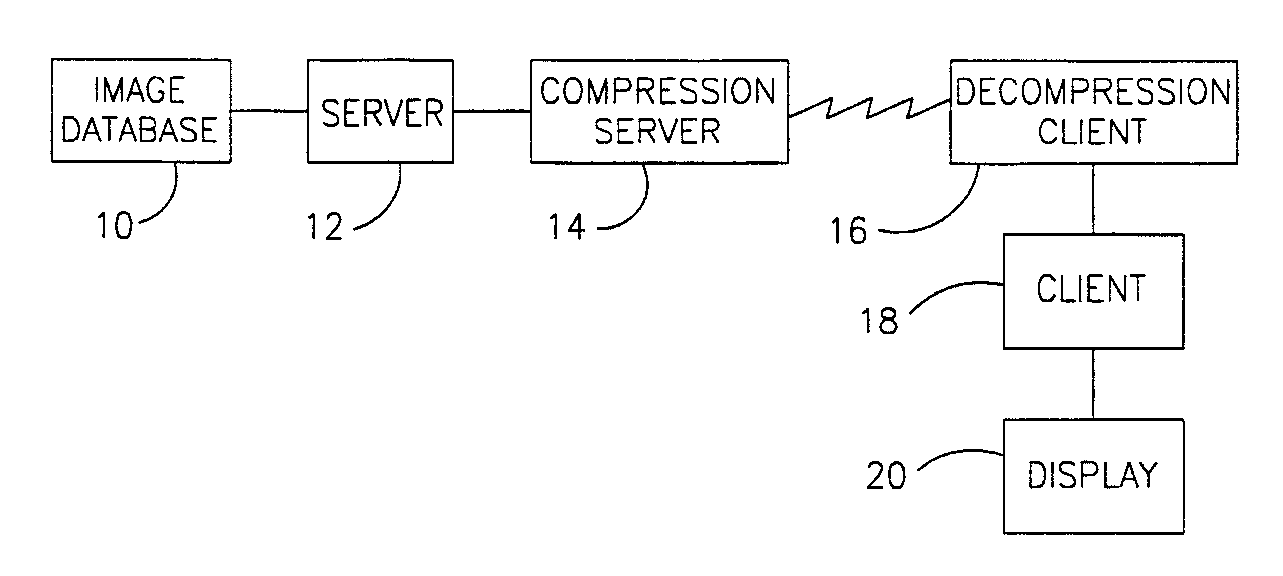
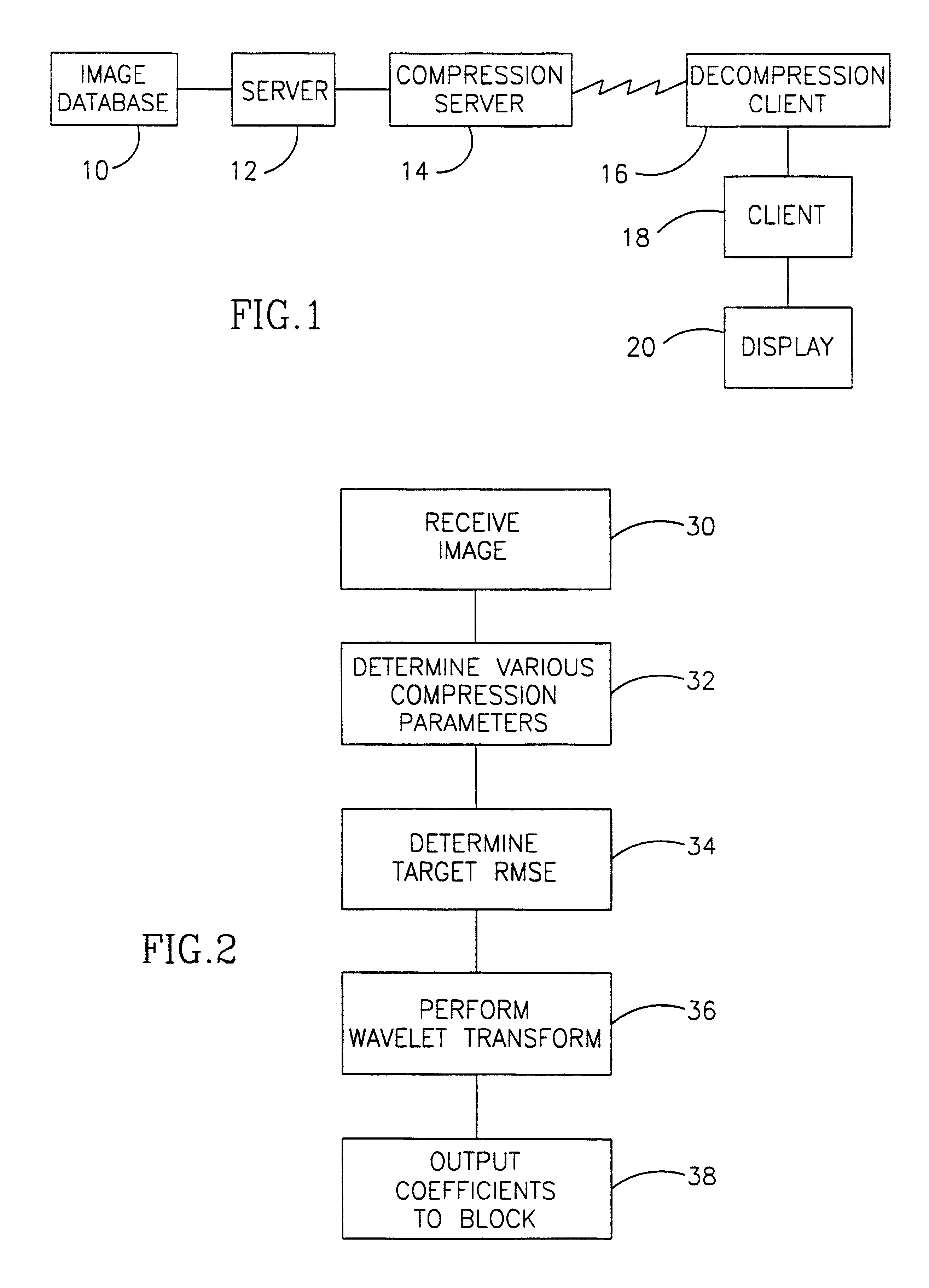
[0101]FIG. 1 is a schematic diagram of a client-server configuration, suitable for practicing a compression method in accordance with a preferred embodiment of the invention. A medical image database 10 includes a plurality of stored images. In a typical medical setting, each of these images may have associated therewith information, including:[0102](a) recommended viewing parameters, including windowing parameters;[0103](b) image acquisition information;[0104](c) image modality;[0105](d) required diagnosis;[0106](e) previously used viewing parameters; and[0107](f) additional information, for example as defined in the DICOM standard.

[0108]A client 18 requests a specific image from a server 12, which then retrieves the requested image from database 10. A compression-server 14 compresses the image and transmits the compressed image to a decompression-client 16, which decompresses the image and passes it to client 18. The decompressed image is then typically displayed on a display 20, ...


PUM


Abstract

A method of compressing a medical image, including:providing a medical diagnostic image, having associated therewith at least one windowing parameter;automatically selecting a desired compression quality, responsive to the at least one windowing parameter; andcompressing the image, using a lossy compression method, such that a decompressed image will have substantially the desired compression quality. Preferably, the at least one windowing parameter is provided by an imaging technician. Preferably, the compression method is a wavelet compression method.

Description

RELATED APPLICATION[0001]This application is a U.S. National filing of PCT Application PCT / IL98 / 00574, filed Nov. 24, 1998.[0002]This application is a 119(e) of a U.S. Provisional application No. 60 / 109,569 of same title, same inventors and same assignee filed in the U.S. Patent and Trademark Office on Nov. 23, 1998, the disclosure of which is incorporated herein by reference.FIELD OF THE INVENTION[0003]The present invention relates to the field of tele-radiology, and in particular to the compression and transmission of diagnostic quality images.BACKGROUND OF THE INVENTION[0004]It is becoming more common for physicians to require diagnostic quality images to be transmitted, via computer communication methods, from an image server to clients stations, at which there are physicians, over large distances. However, due to the large size of the images, the high level of detail required for diagnosis and the limited bandwidth of computer communication lines, it is difficult to transmit su...

Claims


Application Information

Patent Timeline
Patent Type & Authority Patents(United States)
IPC IPC(8): G06K9/36A61B5/00G06K9/46G06T9/00H04NH04N1/41H04N7/24H04N7/26H04N7/30
CPCH04N19/172H04N19/63H04N19/60H04N19/103H04N19/132H04N19/136H04N19/154H04N19/162H04N19/164H04N19/184H04N19/423H04N19/124H04N19/14H04N19/17H04N19/115H04N19/117H04N19/147H04N19/149H04N19/174H04N19/176H04N19/18H04N19/196H04N19/61G06T9/007
Inventor BURAK, YORAMNIZRY, RONENBENJAMIN, MENASHE
Owner ALGOTEC SYST
Why Eureka
Try Eureka