
Drive axle assembly with insert

a technology of drive axles and inserts, which is applied in the direction of gearing details, drip or splash lubrication, machines/engines, etc., can solve the problems of metal particles produced in the lubricant, undesirable wear of the gear train, and foundry sand

Inactive Publication Date: 2005-09-06
DANA HEAVY VEHICLE SYSTEMS GROUP LLC
View PDF20 Cites 32 Cited by
  • Summary
  • Abstract
  • Description
  • Claims
  • Application Information

AI Technical Summary

Benefits of technology

The present invention provides an insert that can be placed within a gear housing to displace lubricant and push it towards the bearings of the half shafts. The insert can also have pockets with magnets to hold contaminants in the lubricant. This results in better lubrication for the drive axle assembly.

Problems solved by technology

Foundry sand may be present due to insufficient cleaning of the housing before the axle assembly operation.
Working of the various gears within the gear housing can cause particles of metal to be produced within the lubricant.
Such particles can cause undesirable wear upon the gear train and inhibit the proper flow of lubricant throughout the axle assembly.

Method used


Image

  • Drive axle assembly with insert
  • Drive axle assembly with insert
  • Drive axle assembly with insert

Examples


Embodiment Construction

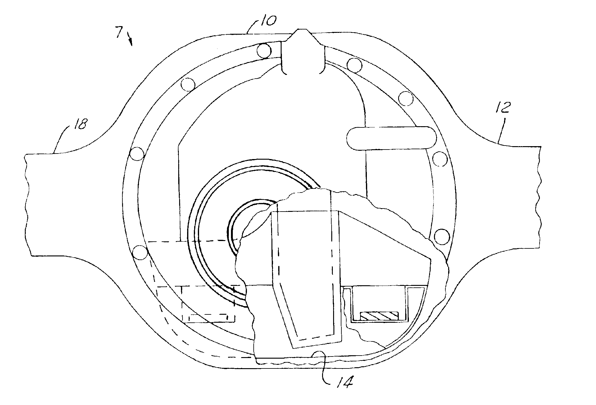
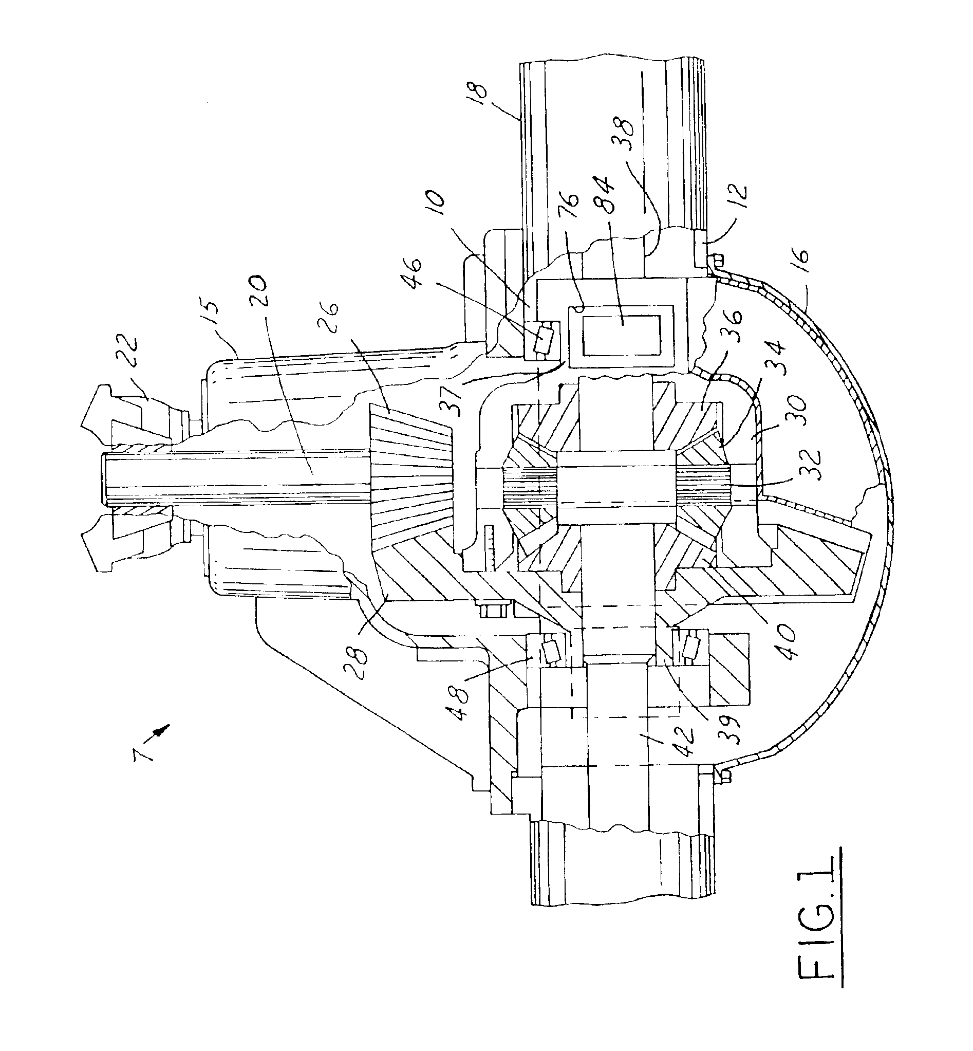
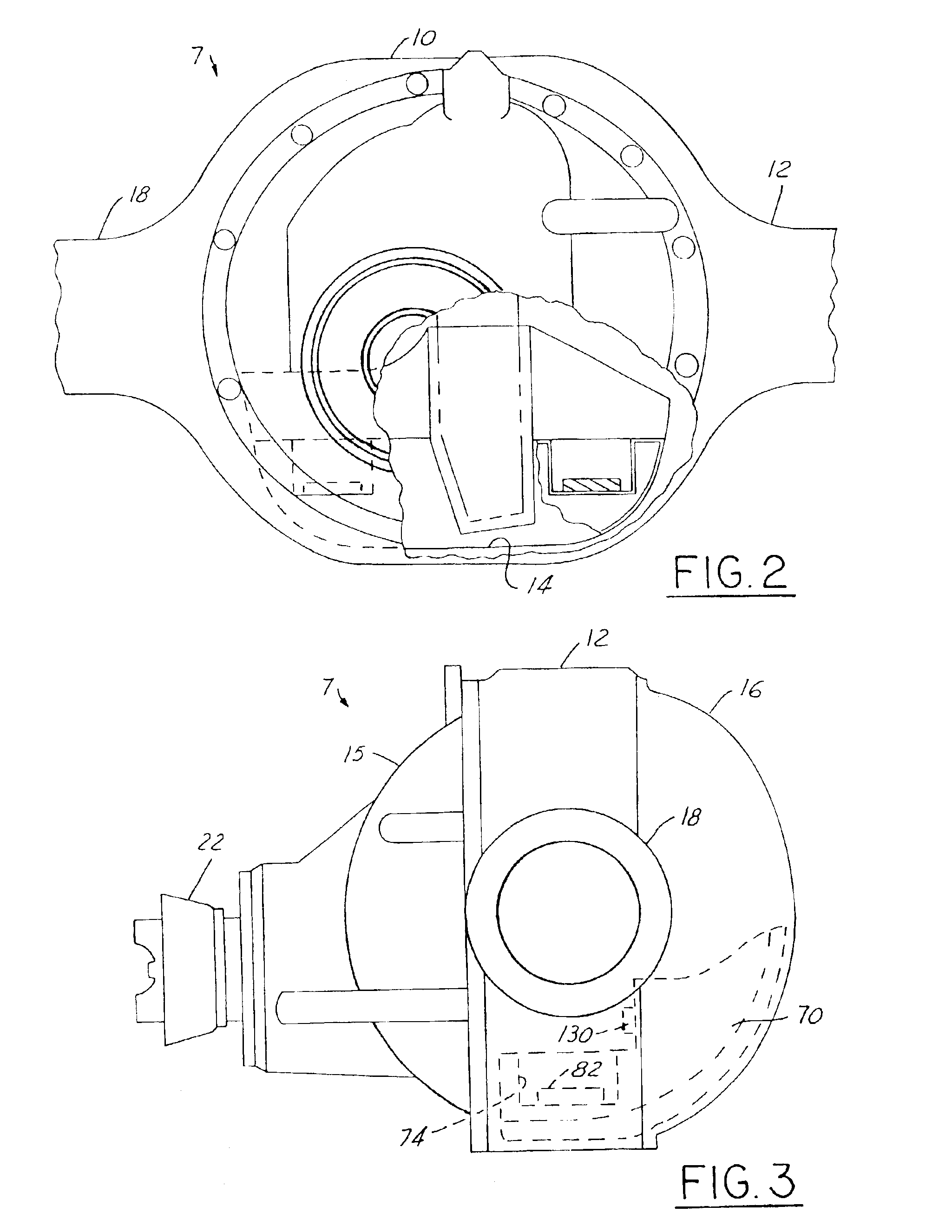
[0018]Referring to FIGS. 1-5 the drive axle assembly 7 of the current invention has a gear housing 10. The gear housing 10 is integrally formed by an axle housing 12. The axle housing 12 has a front opening 14. The front opening 14 is enclosed by an enclosure member provided by a carrier 15. The axle housing 12 has a rear opening which is covered by an enclosure member provided by an axle housing cover 16. The axle housing 12 has two integrally formed side arms 18. The gear housing 10 along with its connected enclosure members provided by carrier 15 and axle housing cover 16 provides a lubricant reservoir which will be filled with a lubricating oil.

[0019]Rotatably mounted by front and rear bearings (not shown) within the carrier 15 is an input shaft 20. The input shaft 20 is connected with a yoke or flange 22 to receive torsional force from a drive shaft (not shown) of the vehicle. A rear end of the input shaft 20 is connected with a pinion gear 26. Pinion gear 26 is meshed with a r...


PUM


Abstract

A drive axle assembly is provided which includes a gear housing and differential gear set. An insert is provided which is disposed in a lubricant reservoir of the gear housing. The insert directs lubricant away from the reservoir upon rotation of the differential gear housing.

Description

BACKGROUND OF THE INVENTION[0001]1. Field of the Invention[0002]The field of the present invention is drive axle assemblies and more particularly, drive axle assemblies commonly used in trucks.[0003]2. Discussion of Related Art[0004]Many trucks have a drive axle assembly which includes a gear housing provided by an integral axle housing. The gear housing has a front opening to allow for connection of its input shaft with an exterior yoke or flange which is in turn connected with a drive shaft of the vehicle. The input shaft powers a pinion gear which is meshed with a ring gear. The ring gear is connected with a differential carrier. The carrier is connected with a spider having spider gears rotatively mounted thereon. The spider gears are meshed with opposing side gears. The side gears are connected with two side journals or half shafts. The half shafts extend laterally outward from the gear housing to drive the drive wheels of the vehicle. The gear housing is either integral with o...

Claims


Application Information

Patent Timeline
Patent Type & Authority Patents(United States)
IPC IPC(8): F16H57/04F16H57/02
CPCF16H57/0483F16H57/0421F16H57/02F16H57/0404Y10T74/2186F16H2057/02052
Inventor SLESINSKI, STEVEN G.
Owner DANA HEAVY VEHICLE SYSTEMS GROUP LLC
Learn More