Hand-held fluid dispenser system and method of operating hand-held fluid dispenser systems

a dispenser system and hand-held technology, applied in the direction of liquid transferring devices, liquid handling, instruments, etc., can solve the problems of mechanical switches with poor reliability of operation, inadvertent movement of the syringe tip from the desired dispensing location, fatiguing and stressful to the operator, etc., to improve the dispensing accuracy, improve the hand grip, and reduce fatigue and stress for the operator

Inactive Publication Date: 2005-09-06
NORDSON CORP
View PDF24 Cites 31 Cited by
  • Summary
  • Abstract
  • Description
  • Claims
  • Application Information

AI Technical Summary

Benefits of technology

[0006]The invention provides an improved hand grip for a fluid dispenser system that encourages a neutral hand position when using the holder, thus making the holder more comfortable for the operator. Further, the hand grip does not require the application of a physical force to a mechanical switch actuate the fluid dispenser system, thereby reducing fatigue and stress for the operator. This also eliminates the tendency for an operator to move a nozzle tip of the fluid dispenser system when the physical force is applied, which improves dispensing accuracy. In addition, the hand grip is ergonomically designed to comfortably fit a wide range of hand sizes. Further still, the hand grip does not rely on mechanical switches to actuate the dispensing system, thereby improving its reliability because the proximity switches of the invention lack moving components and cannot be contaminated by dispensed fluid. Thus, the hand grip is comfortable to hold, easy to use, very reliable, less fatiguing and stressful than conventional hand grips, and is especially useful in those applications for fluid dispenser systems where dispensing accuracy and precision are important.

Problems solved by technology

Mechanical switches have a poor reputation for reliability of operation over the long term.
Over an extended period of operation, the requirement of applying a physical force to initiate a dispensing action may be fatiguing and stressful to an operator.
Moreover, applying a physical force to initiate a dispensing action often results in the syringe tip being inadvertently moved from a desired dispensing location.

Method used


Image

  • Hand-held fluid dispenser system and method of operating hand-held fluid dispenser systems
  • Hand-held fluid dispenser system and method of operating hand-held fluid dispenser systems
  • Hand-held fluid dispenser system and method of operating hand-held fluid dispenser systems

Examples


Embodiment Construction

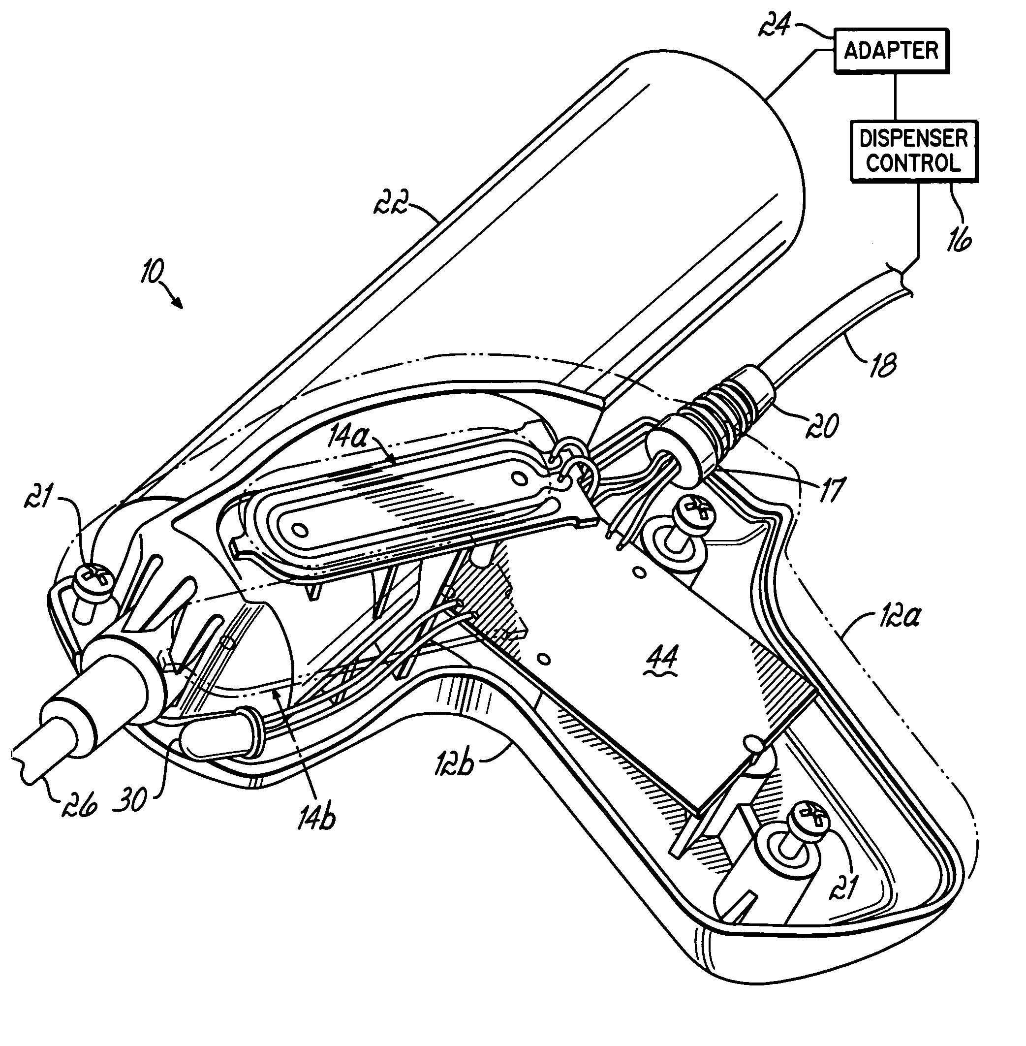
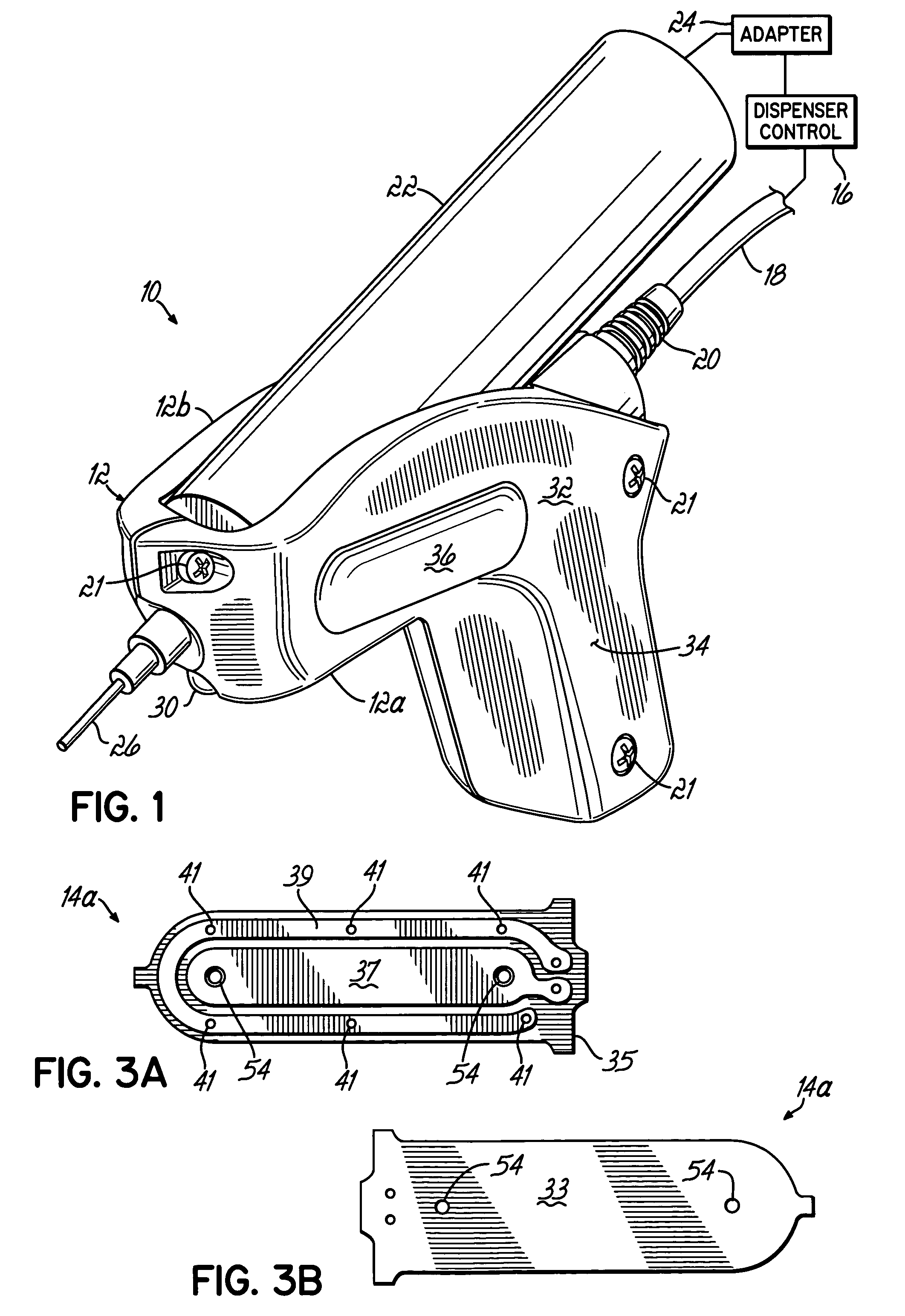
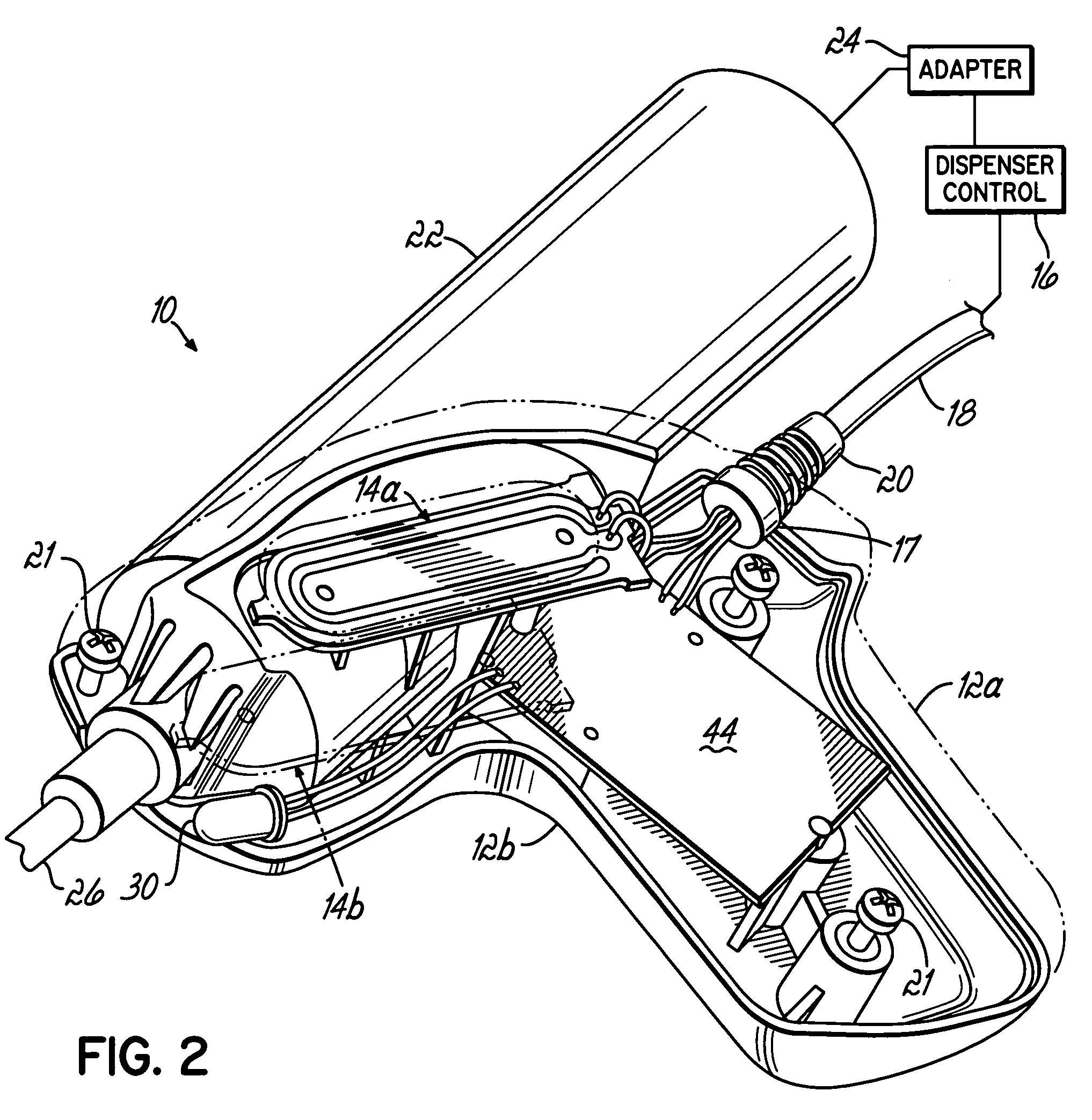
[0016]Referring to FIGS. 1 and 2, a hand grip 10 for use with a fluid dispenser system has an enclosure 12 that sealingly encloses a pair of proximity sensors or switches 14a, 14b and an actuation control 72 (FIG. 4). The actuation control 72 is electrically connected to a dispenser control 16 of the fluid dispenser system via a cable 18 to define the fluid dispenser system. An exemplary dispenser control 16 with which the hand grip 10 may be electrically connected is the family of Ultra™ 2400 Series Dispensing Workstations commercially available from EFD Inc., East Providence, R.I. The point of egress 17 (FIG. 2) of the cable 18 from the enclosure 12 is designed to prevent entanglement with the workpiece intended to receive dispensed fluid and includes an integral overmolded strain relief 20. The enclosure 12 is comprised of two opposing pieces 12a, 12b assembled together with conventional fasteners 21.

[0017]The enclosure 12 supports a fluid container, illustrated as a syringe 22, ...


PUM


Abstract

A hand-held fluid dispenser having an enclosure for supporting a container holding a fluid to be dispensed, and a method of operating such hand-held fluid dispensers. A first proximity sensor is located inside the enclosure immediately adjacent one side of the enclosure, and a second proximity sensor is located inside the enclosure immediately adjacent an opposite side of the enclosure. An actuation circuit is supported inside the enclosure and is electrically connected to the first and second proximity sensors. The actuation circuit produces an actuation signal in response to detecting opposed digits of an operator being simultaneously in close proximity to the first and second proximity sensors.

Description

CROSS-REFERENCE TO RELATED APPLICATIONS[0001]This application claims the benefit of U.S. Provisional Application No. 60 / 525,486 filed on Nov. 26, 2003, the disclosure of which is hereby incorporated by reference herein in its entirety.FIELD OF THE INVENTION[0002]The present invention generally relates to fluid dispenser systems and more particularly, to hand grip for a fluid dispenser system, fluid dispenser systems using the hand grip, and methods of operating such fluid dispenser systems.BACKGROUND OF THE INVENTION[0003]Conventional hand grips for fluid dispenser systems have many different shapes and configurations. With some systems, an operator holds a hand grip housing a fluid cartridge or syringe and the dispensing action is initiated with a foot pedal. With other systems, the fluid syringe is mounted in a hand grip grasped by an operator, and a dispensing action is initiated by the operator activating a finger switch on a side of the fluid dispenser. However, all of the know...

Claims


Application Information

Patent Timeline
Patent Type & Authority Patents(United States)
IPC IPC(8): B05C17/00B05C17/005B05C17/01B05B12/00B67D7/42B67D7/08
CPCB05C17/002B05C17/0133B05B12/00B05C17/00B67D7/08B67D7/42
Inventor BARTON, JR., JOHN D.MENDOZA, JEFFREY
Owner NORDSON CORP
Why Eureka
Try Eureka