Nail clippers

a nail clipper and clipper technology, applied in the field of nail clippers, can solve the problems of inconvenient use for the user, and achieve the effect of clipping the nail with eas

Inactive Publication Date: 2005-09-13
CHOI YOUNG SIK +1
View PDF9 Cites 15 Cited by
  • Summary
  • Abstract
  • Description
  • Claims
  • Application Information

AI Technical Summary

Benefits of technology

[0004]To solve the above-described problems, it is an object of the present invention to provide nail clippers that are provided with an operation grip part pressurizing a cutting edge that can be freely rotated with respect to a body and moved along the surface of the body, thereby allowing a user to clip his or her nails with ease.
[0011]According to the present invention, one of the upper and lower steel plates forms a bent portion that is adjacent to the one cutting edge on the sides of the body and bent toward the space portion between the upper and lower steel plates, the bent portion forming a coupling hole through which a coupling member is inserted, the coupling member connected with a stop bar on a front end thereof, for moving forwardly and backwardly in a width direction of the body corresponding to the length of the nail, thereby protecting the nail from coming in the space portion between the upper and lower steel plates.
[0015]According to the present invention, the lower steel plate of the body forms a support part that is protruded upwardly on the outer peripheral portion of the through hole thereof, the support part stopping the descending of the upper steel plate when the upper steel plate is descended by the pressurizing of the operation grip part so that the cutting edges of the upper and lower steel plates are in sufficiently close contact with the nail to clip the nail, thereby protecting the cutting edges from being damaged.

Problems solved by technology

However, since the conventional nail clippers work only in a manner that the pressurizing bar is positioned in a straight line against the body, a user should turn the body along his or her nails rounded in the arc shape at the time of nail-clipping, which of course makes him or her feel that it is inconvenient to use.

Method used


Image

  • Nail clippers
  • Nail clippers
  • Nail clippers

Examples


Embodiment Construction

[0028]Now, an explanation of the preferred embodiment of the present invention will be made with reference to accompanying drawings.

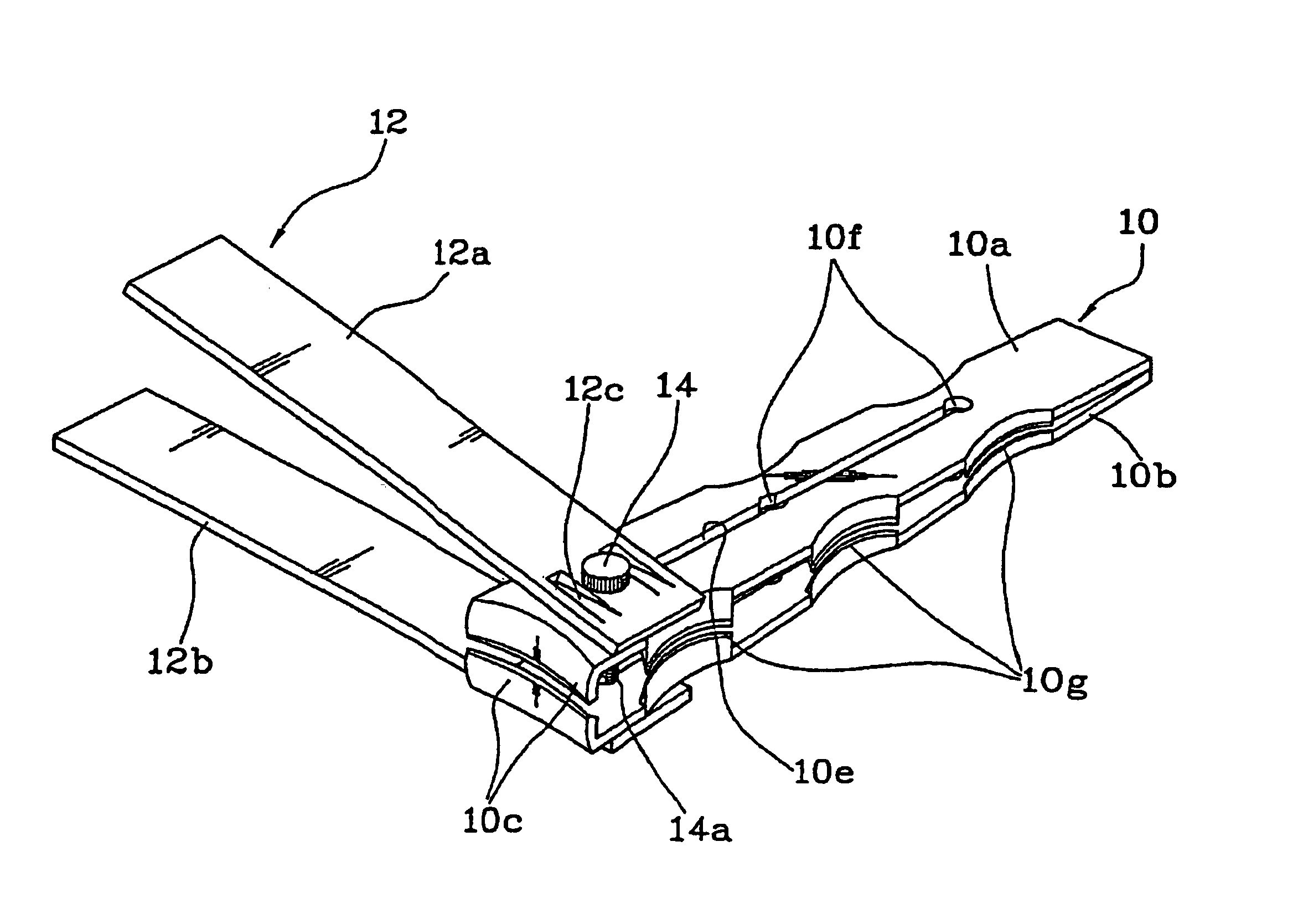
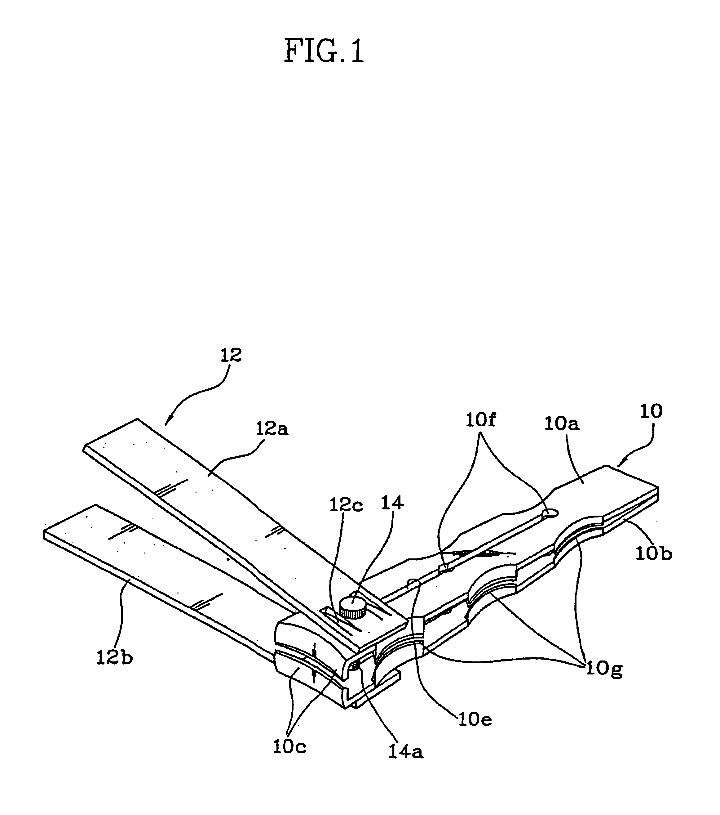
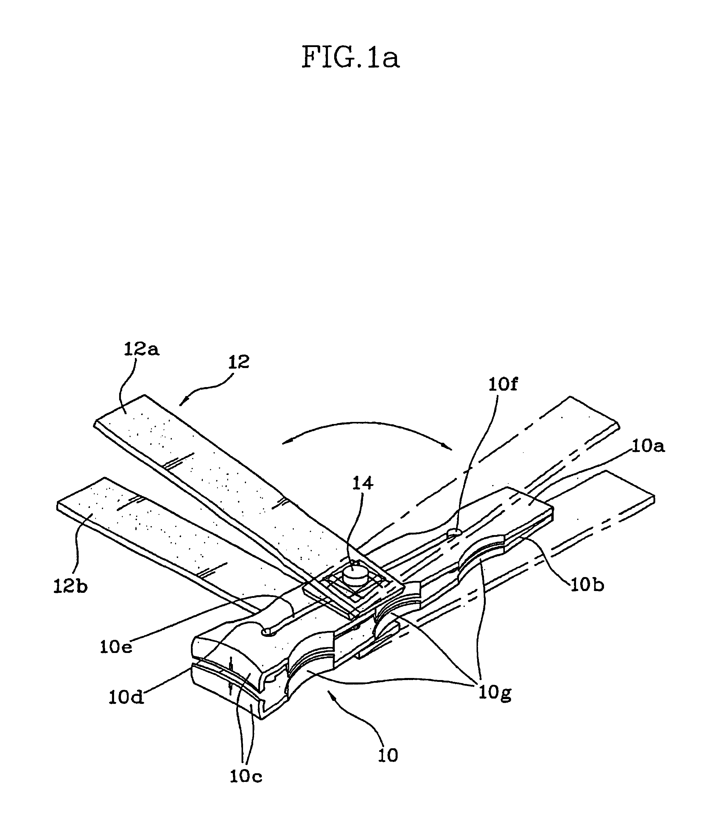
[0029]As shown in FIGS. 1 and 1a, a nail clipper according to the present invention includes a body 10 having upper and lower steel plates 10a and 10b, an operation grip part 12 disposed in close contact with the outsides of the upper and lower steel plates 10a and 10b, and a support shaft 14 for supporting the operation grip part 12 such that the operation grip part 12 rotates with respect to the body 10.

[0030]The upper and lower steel plates 10a and 10b of the body 10, which are generally rectangular shaped members, are connected on one end parts and spaced by a predetermined distance on another end parts, each provided with cutting edges 10c. The end parts provided with the cutting edge 10c thereon come in contact with each other by the application of an external force and are elastically opened, then. The upper and lower steel plates 10a and 10b are...


PUM


Abstract

A nail clipper has an operation grip part pressurizing a cutting edge that can be freely rotated with respect to the body and moved along the surface of the body, thereby allowing a user to clip his or her nails with ease.

Description

TECHNICAL FIELD[0001]The present invention relates to nail clippers, and more particularly, to nail clippers that are provided with an operation grip part pressurizing a cutting edge that can be freely rotated with respect to a body and moved along the surface of the body, thereby allowing a user to clip his or her nails with ease.BACKGROUND ART[0002]A nail clipper generally includes a body that has upper and lower steel plates connected on one end parts and opened on the other end parts on which are formed a cutting edge, and a pressurizing bar placed on one of the upper and lower steel plates of the body and thus connected with the body by virtue of a support shaft. In operation, if the pressurizing bar is depressed, the support shaft is pulled by the operation of the lever protrusion of the pressurizing bar, which allows the cutting edges to become in contact with each other so that the nail between the cutting edges can be clipped.[0003]However, since the conventional nail clipp...

Claims


Application Information

Patent Timeline
Patent Type & Authority Patents(United States)
IPC IPC(8): A45D29/00A45D29/02
CPCA45D29/02
Inventor CHOI, YOUNG-SIKCHOI, YONG-SIK
Owner CHOI YOUNG SIK
Why Eureka
Try Eureka