Snowplow assembly

a technology of snowplows and parts, applied in snow cleaning, way cleaning, construction, etc., can solve the problem of exposing such a lightweight pickup to excessive loads

Inactive Publication Date: 2005-09-13
DOUGLAS DYNAMICS
View PDF37 Cites 82 Cited by
  • Summary
  • Abstract
  • Description
  • Claims
  • Application Information

AI Technical Summary

Benefits of technology

[0007]In another aspect, a snowplow assembly comprises a lift frame and an A-frame operably pivotally connected together, an actuator operably connected between the lift frame and A-frame for effecting relative pivotal movement between the lift frame and the A-frame, a plow blade operably pivotally connected to the A-frame, and a non-metallic resilient endless loop operably connected between the plow blade and A-frame; the pivotal connection of the plow blade to the A-frame in combination with the resilient loop provides a trip function of the plow blade.

Problems solved by technology

However, conventional detachable snowplow assemblies, built for full size pickups and / or SUV's, can subject such a lightweight pickup to excessive loads due to the weight of the snowplow assembly.

Method used


Image

  • Snowplow assembly
  • Snowplow assembly
  • Snowplow assembly

Examples


Embodiment Construction

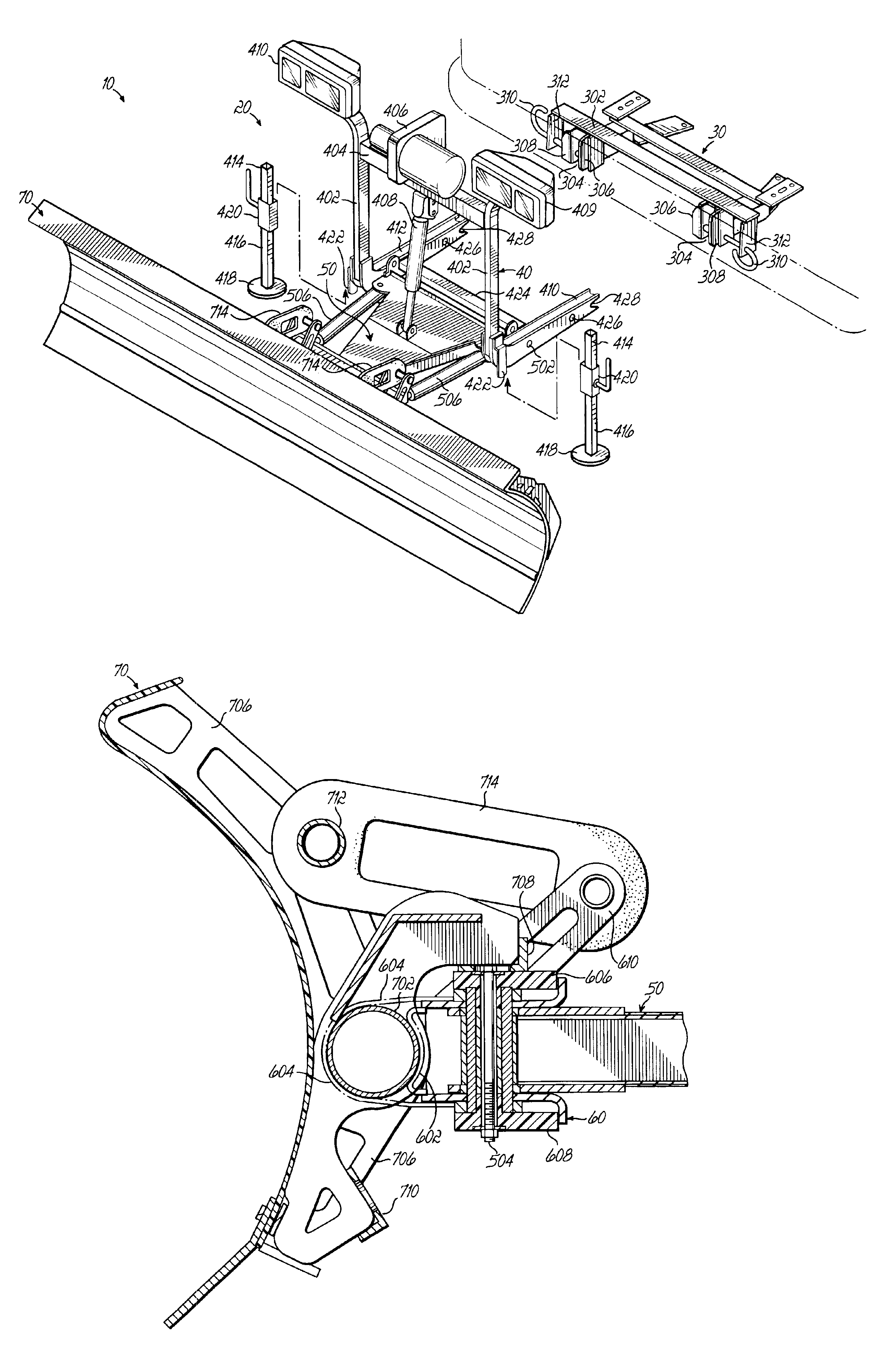
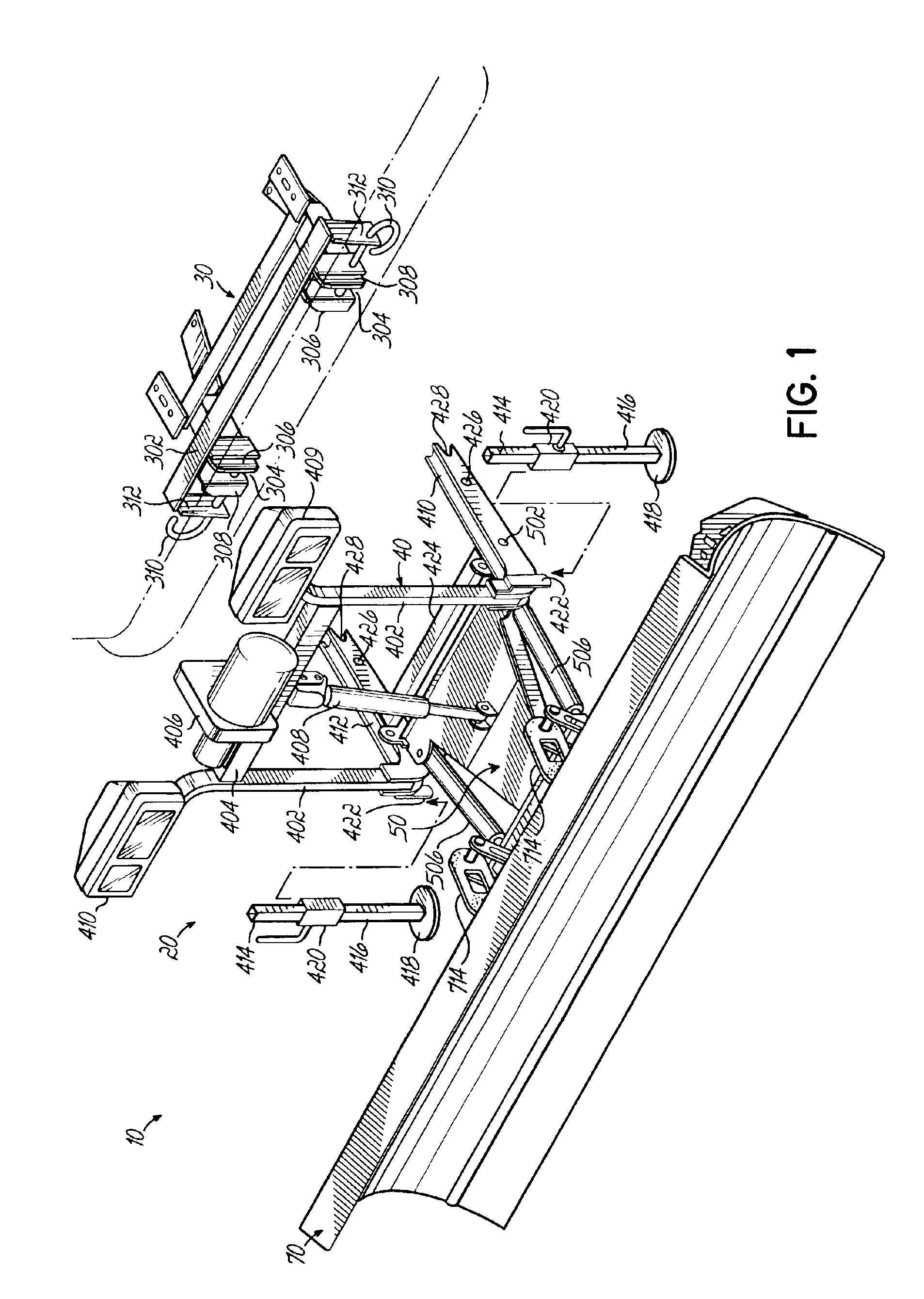
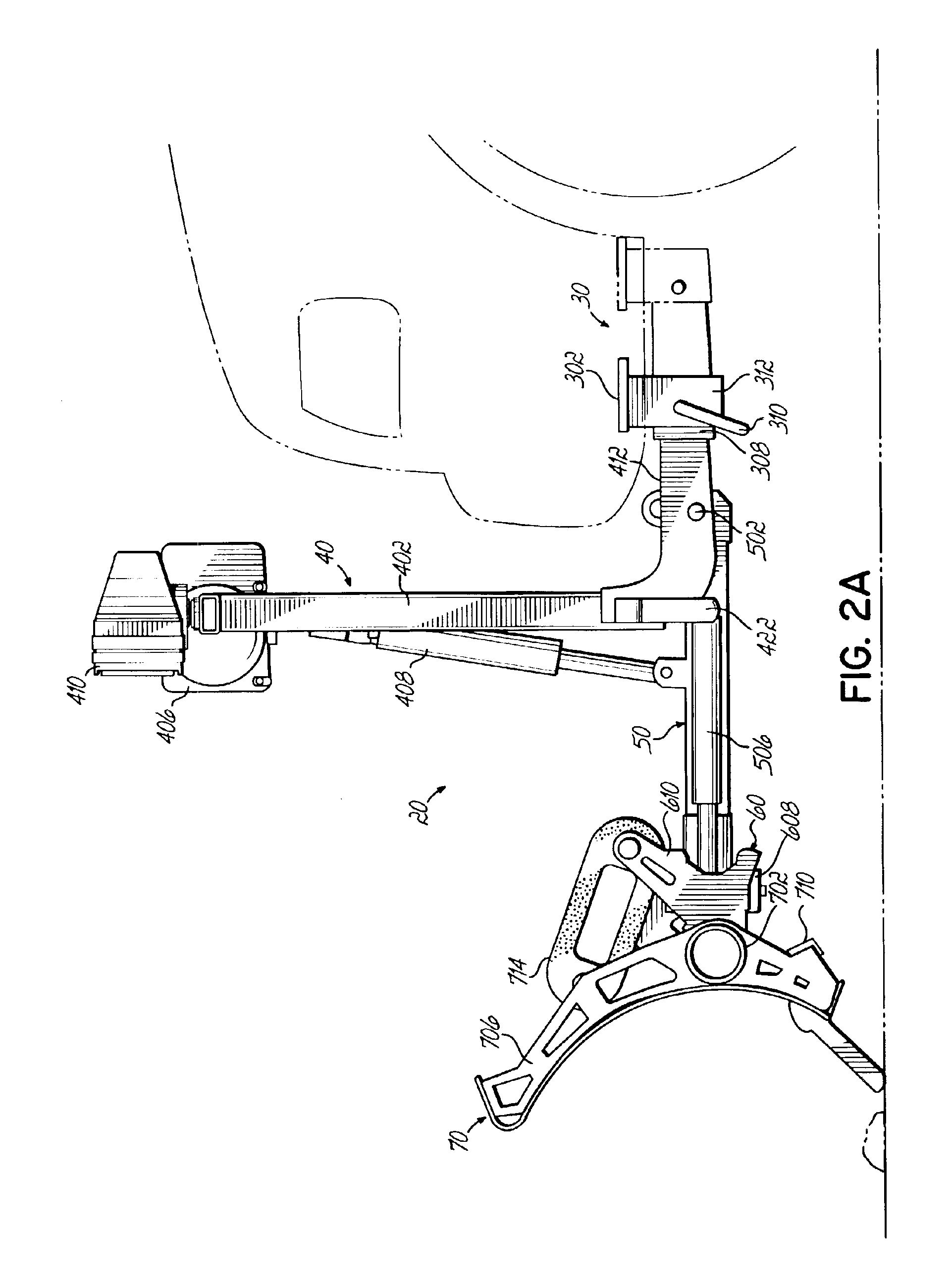
[0017]Referring first to FIG. 1, there is illustrated a snowplow and mount assembly 10 according to the principles of the present invention. The assembly 10 includes a snowplow assembly 20 and a vehicle mount assembly 30.

[0018]Referring to FIGS. 1-3, snowplow assembly 20 can include a lift frame 40, an A-frame 50, a quadrant 60 and a plow blade 70. Lift frame 40 can include a pair of upwardly extending supports 402 interconnected by an upper laterally extending support 404. Lateral extending support 404 can support a hydraulic motor 406 to supply hydraulic fluid to a hydraulic lift cylinder 408, also supported by support 404 and connected to A-frame 50. A pair of headlamps 410 can be supported by the upwardly extending supports 402. Lift assembly 40 can further include a pair of rearwardly extending arms 412 which are adapted to be removably secured to mount frame assembly 30, as will be described below. Lift assembly 40 can further include a pair of support stands 414 each of which...


PUM


Abstract

A snowplow assembly comprises a lift frame and A-frame operably pivotally connected together and an actuator operably connected between the lift frame and A-frame for effecting relative pivotal movement between the lift frame and A-frame. A plow blade includes a blade frame. The blade frame includes a tube of circular cross section which is operably pivotally connected to the A-frame. The tube is pivotally received by a quadrant, which is operably connected to the A-frame. A resilient element is operable between the blade frame and A-frame normally biasing a lower edge of the plow blade forwardly. The resilient element is an elastomeric loop. The pivotal connection of the plow blade to the A-frame in combination with the resilient element provides a trip function of the plow blade. The plow blade is a composite. The circular tube of the blade frame provides torsional stiffness to the composite blade.

Description

FIELD OF THE INVENTION[0001]This invention relates to snow removal equipment and, more particularly, to a snowplow assembly of lightweight construction.BACKGROUND OF THE INVENTION[0002]Passenger vehicles have been used for sometime as a means for plowing snow by utilizing snowplow assemblies which are detachably mounted to the passenger vehicle. The passenger vehicles of choice for such plowing have included full size pickups and sport utility vehicles (“SUV's”.)[0003]Efforts are underway to utilize smaller passenger vehicles for plowing snow. For example, it is desirable to be able to utilize a lightweight pickup as the vehicle for plowing snow with the detachably mountable snowplow assembly. However, conventional detachable snowplow assemblies, built for full size pickups and / or SUV's, can subject such a lightweight pickup to excessive loads due to the weight of the snowplow assembly.[0004]Accordingly, it is desirable to redesign the conventional passenger vehicle mountable snowpl...

Claims


Application Information

Patent Timeline
Patent Type & Authority Patents(United States)
IPC IPC(8): E01H5/06E01H5/04
CPCE01H5/06E01H5/063
Inventor GOY, MICHAELKLUCK, SCOTTLEBLOND, ANDRE
Owner DOUGLAS DYNAMICS
Why Eureka
Try Eureka