Eureka AIR delivers breakthrough ideas for toughest innovation challenges, trusted by R&D personnel around the world.

Motorized light bulb changer

Inactive Publication Date: 2005-09-13
WAGIC
View PDF97 Cites 21 Cited by
  • Summary
  • Abstract
  • Description
  • Claims
  • Application Information

AI Technical Summary

Benefits of technology

[0008]In one aspect of the present invention is a tool for selectively tightening and loosening a light bulb. The tool comprises means for clasping the light bulb. The clasping means is configured to have an adjustable dimension that is for clasping a correspondingly sized light bulb. The tool includes means for activating the clasping means. The activating means is configured for remote communication with the clasping means, wherein the activating means sends control communications to move the clasping means in a first direction and a second direction. The tool further comprises means for setting the clasping means in a desired configuration to engage the light bulb. The setting means is coupled to the clasping means. The setting means further comprises a means for varying the adjustable dimension. The varying means is coupled to the activating means. The control communications are preferably sent wirelessly from the activating means to the clasping means. In an alternative embodiment, the clasping means and the activating means are coupled to one another by a cable. The clasping means and the activating means are preferably coupled to a tubular member. The tool further comprises means for securing the wire to the tubular member, wherein the overall length of the tubular member is able to be selectively adjusted. The means for activating is preferably powered by a DC voltage source and alternately by an AC voltage source.
[0009]In another aspect of the invention is a light bulb changing tool that comprises a motorized clasping mechanism that is configured to engage a light bulb. The motorized clasping mechanism is configured along an axis and to actuate in a first direction and a second direction. The tool includes an electronic drive unit that is configured for remote communication with the motorized clasping mechanism. The electronic drive unit sends control communications to drive the motorized clasping mechanism to selectively move in the first direction and the second direction. The tool further comprises an arm member that positions the motorized clasping mechanism in a desired configuration to engage the light bulb. The arm

Problems solved by technology

One such problem is accessibility.
Another problem stems from the variety of angles from which bulbs must be extracted and replaced from these remote locations, such as from chandeliers and hanging light arrangements.
Another problem is the adjustability of the handle to reach light bulbs at varying distances.
Further, the handle in this patent does not have a flexible arm for reaching light bulbs that are at an angle.
However, the device taught by Maki, by having a fixed rod, does not allow the user to adjust the rod to different heights.
This is disadvantageous to the user, because the cup is not adjustable to engage different sized light bulbs.
Although this light bulb changer allows the user to bend the arm to engage light bulbs at different angles, the light bulb changer does not allow the user to adjust the handle to different heights.
Further, the light bulb changer taught by Negley does not allow the user to adjust the mechanism to fit differently sized light bulbs.
However, the pivoting section is locked by tightening the clamp screw, which is burdensome on the user, because the user must use a screw driver, or some other external tool, to lock the pivoting shaft.
Further, the rods taught in this patent are also adjustable to reach light bulbs at different heights, but the mechanism to lock the rods at a desired height is limiting.
Therefore, the user can only adjust the rod at certain heights, which is burdensome if the light bulb is at a height that does not correspond to any of the positions available on the rod.

Method used


Image

  • Motorized light bulb changer
  • Motorized light bulb changer
  • Motorized light bulb changer

Examples


Embodiment Construction

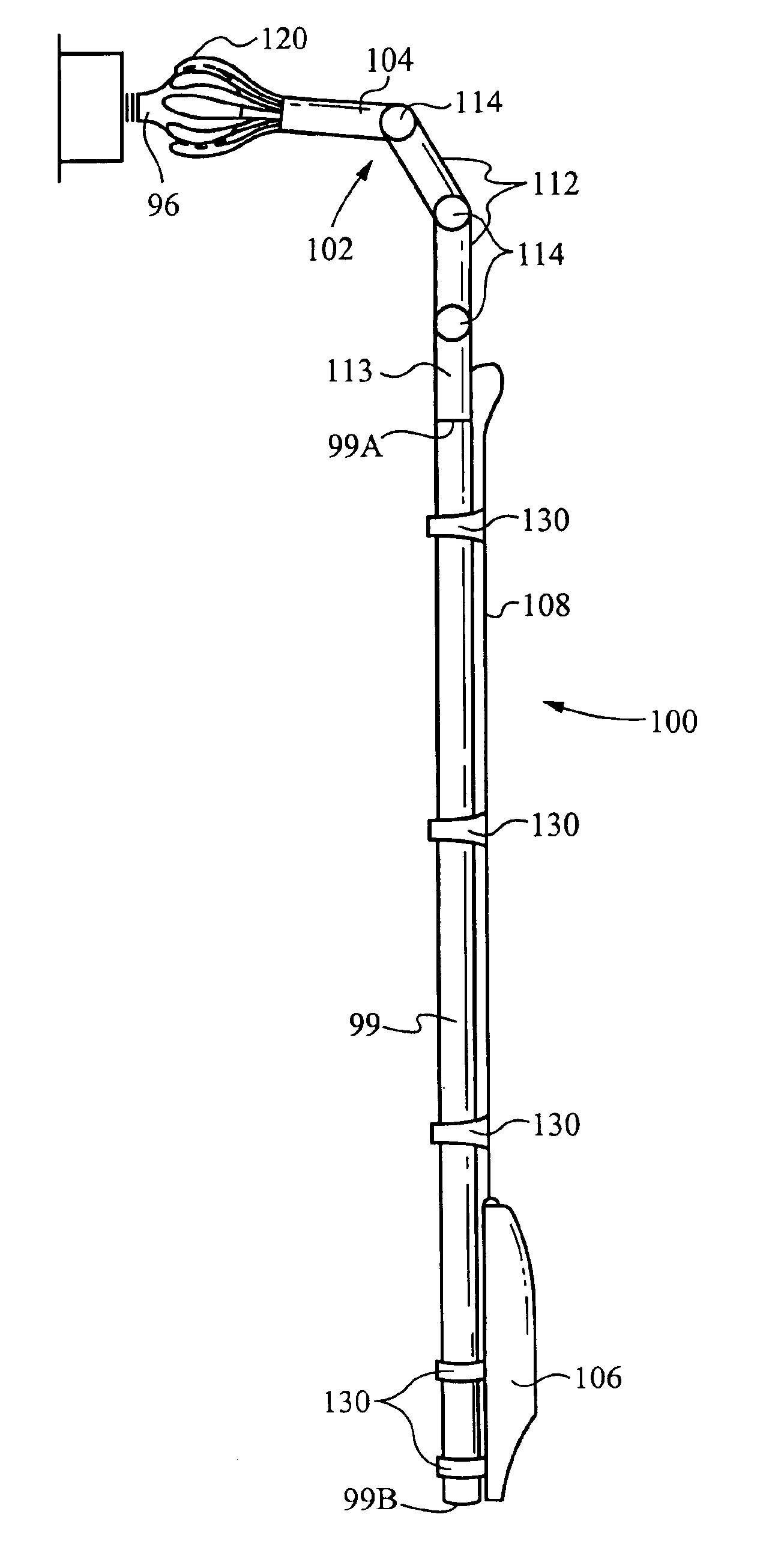
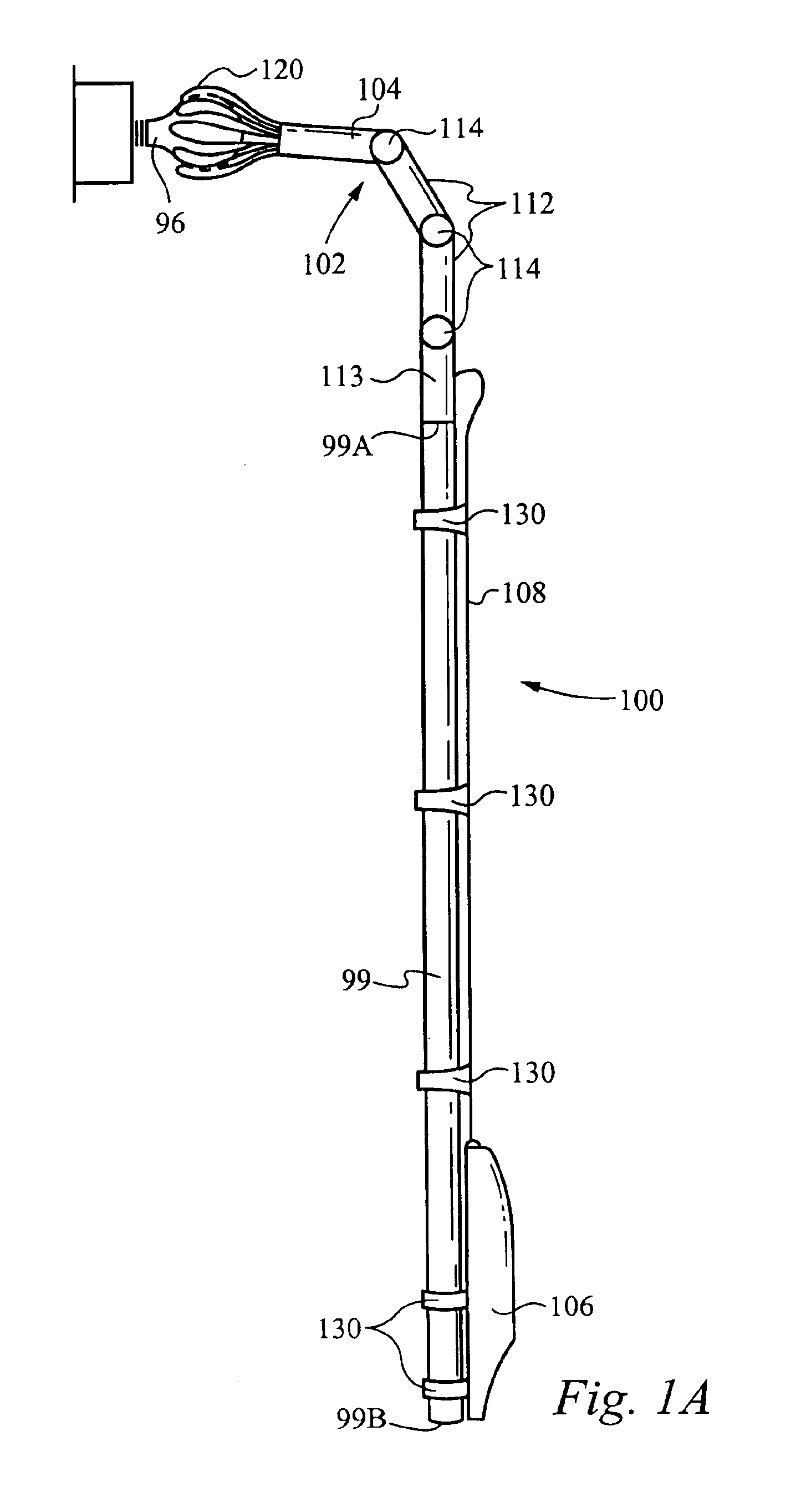
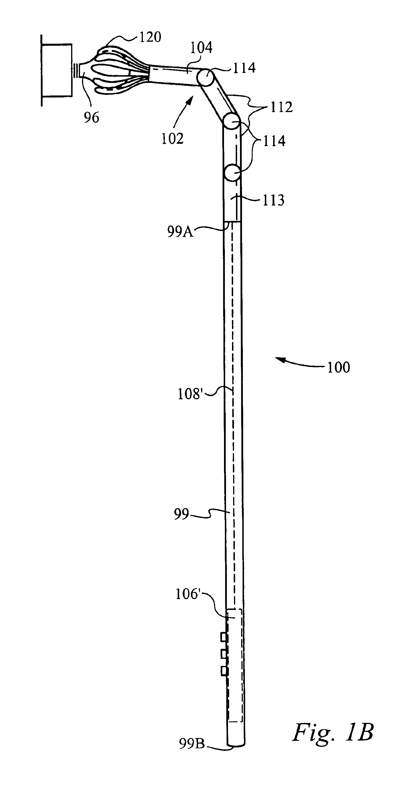
[0018]FIG. 1A illustrates a side view of an alternative embodiment of the motorized light bulb changer device with pole in accordance with the present invention. Generally, the motorized light bulb changer 100 includes a clasping mechanism 102 having a set of fingers 120, a motor unit 104, an arm unit 112 having a pair of arm members 112A and 112B (FIG. 2) and a connecting arm 113. In addition, the light bulb changer 100 includes a drive or power unit 106, whereby the drive unit 106 is coupled to the clasping mechanism 102 by a cable 108. As will be described in detail below, in the preferred embodiment of the present invention, the drive unit 106 communicates wirelessly to control the self-powered clasping mechanism 102. The motorized light bulb changer 100 shown in FIG. 1A is coupled to a pole 99 which allows the user to change light bulbs 96 held at a variety of angles and heights, that are otherwise inaccessible from ground level. It is preferred that the length of the pole 99 b...


PUM


Abstract

A light bulb changing tool comprising a motorized clasping mechanism configured to engage a light bulb, the motorized clasping mechanism configured along an axis, the motorized clasping mechanism configured to actuate in a first direction and a second direction; and a electronic drive unit configured to remotely communicate with the motorized clasping mechanism, wherein the electronic drive unit sends control signals to drive the motorized clasping mechanism to selectively move in the first direction and the direction. The tool further comprising an arm member for positioning the motorized clasping mechanism in a desired configuration to engage the light bulb, wherein the arm member is coupled to the motorized clasping mechanism. The motorized clasping mechanism further comprises a rotator mechanism configured to rotate the motorized clasping mechanism in the first direction about the axis.

Description

[0001]This Patent Application is a continuation of co-pending U.S. patent application Ser. No. 10 / 218,404 filed on Aug. 12, 2002, now issued as U.S. Pat. No. 6,739,220.FIELD OF THE INVENTION[0002]The present invention relates to a remote access tool. More specifically, the present invention relates to a motorized device designed to remove and replace light bulbs which are held at a variety of angles and heights and are otherwise inaccessible from ground level.BACKGROUND OF THE INVENTION[0003]Numerous light bulb removal tools have been patented which alleviate the problems associated with replacing light bulbs from remote locations. One such problem is accessibility. Overhead lights are purposefully positioned out of reach to minimize risks associated with heat burns and unintentional contact which could result in globe glass breakage. Another problem stems from the variety of angles from which bulbs must be extracted and replaced from these remote locations, such as from chandeliers...

Claims


Application Information

Patent Timeline
IPC IPC(8): B25B13/00B25B13/48B25B21/00B25B9/00H01J9/00H01K3/32
CPCB25B9/00B25B13/48H01K3/32B25B21/002H01J9/003B25B13/481
Inventor JOHNSON, RONALD L.SUGANO, NORIO
Owner WAGIC
Why Eureka
Eureka Blog
Learn More